Controller, chip and method for eliminating current ripple of LED driving system
A technology of LED drive and system current, applied in the direction of electric light source, electrical components, circuit layout, etc., can solve the problems of eliminating ripple and inability to achieve, and achieve the effect of eliminating current ripple
- Summary
- Abstract
- Description
- Claims
- Application Information
AI Technical Summary
Problems solved by technology
Method used
Image
Examples
Embodiment 1
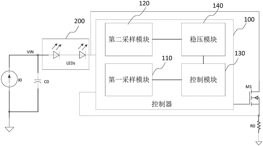
[0048] This embodiment discloses a controller 100 for eliminating the current ripple of the LED driving system. The following uses a MOS transistor as the first power transistor for illustration. In other implementations, the first power transistor can also be a triode or Other types of power tubes. Such as image 3 As shown, the controller 100 is electrically connected to the output terminal of the LED load 200, the first sampling resistor R0 and the first power transistor M1. The controller 100 is used to sample the voltage V at the output terminal of the LED load 200 DRAIN , the voltage V across the first sampling resistor R0 CS and the drain voltage of the first power transistor M1, and the drain voltage of the first power transistor M1 is the same as the voltage at the output terminal of the LED load 200, that is, the drain voltage of the first power transistor M1 is V DRAIN . Further, the controller 100 according to the voltage V of the output terminal of the LED loa...
Embodiment 2
[0077] This embodiment discloses a method for eliminating current ripple in an LED drive system, which uses the controller disclosed in Embodiment 1:
[0078] First, use the controller to sample the voltage V at the output terminal of the LED load 200 DRAIN , the voltage V across the first sampling resistor R0 CS and the drain voltage V of the first power transistor M1 DRAIN , and according to the voltage V at the output of the LED load 200 DRAIN and the voltage V across the first sampling resistor R0 CS generate the first voltage signal V DV1 ; According to the drain voltage V of the first power transistor M1 DRAIN generate the second voltage signal V DV2 ; Then, the controller again according to the first voltage signal V DV1 and the voltage across the first sampling resistor V CS Generate control signal V GATE , so as to control the conduction state of the power transistor M0 connected to the LED load 200, so that the first voltage signal V DV1 The magnitude of the...
PUM
 Abstract
Description
Claims
Application Information
 - R&D
- Intellectual Property
- Life Sciences
- Materials
- Tech Scout
- Unparalleled Data Quality
- Higher Quality Content
- 60% Fewer Hallucinations
Browse by: Latest US Patents, China's latest patents, Technical Efficacy Thesaurus, Application Domain, Technology Topic, Popular Technical Reports.
© 2025 PatSnap. All rights reserved.Legal|Privacy policy|Modern Slavery Act Transparency Statement|Sitemap|About US| Contact US: help@patsnap.com


