
Drive circuit with ripple current elimination and reduced power consumption

A ripple current and drive circuit technology, applied in the direction of lamp circuit layout, electric light source, light source, etc., can solve the problems of increased power consumption, visual fatigue, increased circuit area and cost, etc., to increase power consumption and eliminate current ripple wave effect

Active Publication Date: 2018-09-18
DIOO MICROCIRCUITS CO LTD
View PDF5 Cites 0 Cited by
  • Summary
  • Abstract
  • Description
  • Claims
  • Application Information

AI Technical Summary

Problems solved by technology

[0002] Generally speaking, in common LED (light emitting diode) drivers, in order to be compatible with high power factor and cost control, it is usually realized by a single-stage PFC (power factor correction) circuit. The output current of this control method includes power frequency current Ripple components, whose frequency is about twice the frequency of the power grid, that is, 100Hz (120Hz), working under such low-frequency stroboscopic conditions for a long time will easily cause human visual fatigue and affect the life of LED lights
[0003] The common way to improve the current ripple is to increase the output filter capacitor used in the driver, but this will increase the circuit area and cost; Significantly increase power consumption, this kind of current ripple improvement method has disadvantages that cannot be ignored

Method used


Image

  • Drive circuit with ripple current elimination and reduced power consumption
  • Drive circuit with ripple current elimination and reduced power consumption
  • Drive circuit with ripple current elimination and reduced power consumption

Examples


Embodiment Construction

[0045] The implementation of the present invention is described below with specific examples, and those skilled in the art can easily understand other advantages and effects of the present invention from the content disclosed in this specification. The present invention can also be implemented or applied through other different specific embodiments.

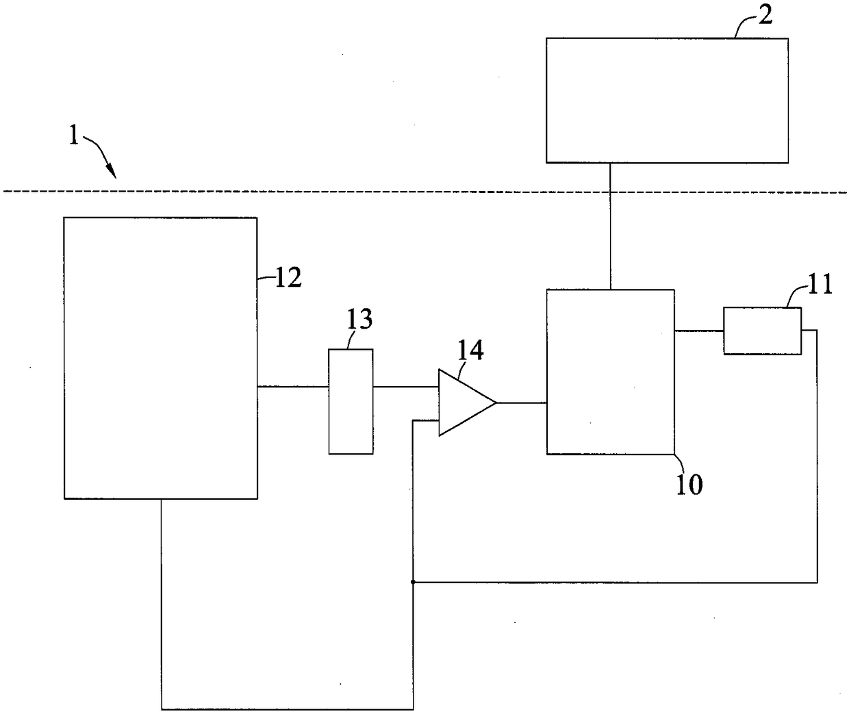
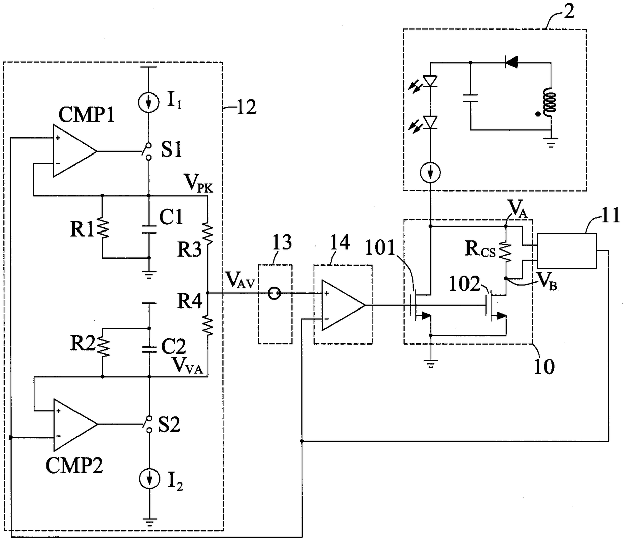
[0046] see figure 1 , which is a schematic structural diagram of a driving circuit with ripple current elimination and power consumption reduction in the present invention. Such as figure 1 As shown, the drive circuit 1 with ripple current elimination and power consumption reduction of the present invention is connected with an external circuit 2 with current ripple, and is characterized in that it includes an output power module 10, a high-side current detection module 11, an average value A sampling module 12 , a bias voltage module 13 and an operational amplifier 14 .

[0047] The output power module 10 is used to be connec...


PUM


Abstract

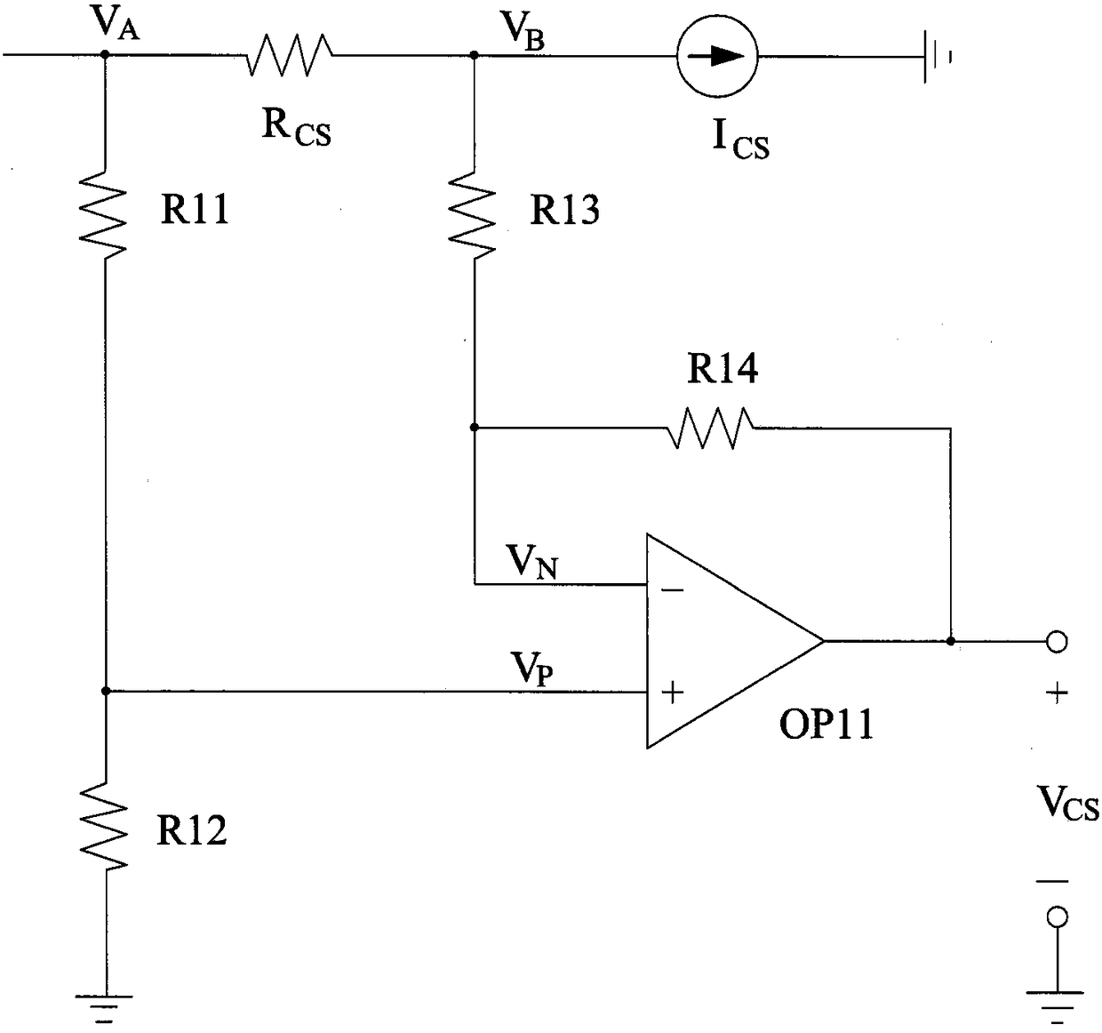
The present invention provides a driving circuit with ripple current elimination and power consumption reducing. The driving circuit with ripple current elimination and power consumption reducing is connected with the external circuit with a current ripple (such as a LED circuit), and comprises an output power module, a high-end current detection module, a mean value sampling module, a bias voltage module and an operational amplifier. The output power module is connected with the external circuit and is provided with an output transistor device to control the output of the external circuit; the high-end current detection module is provided with a sampling resistor connected with the output power module and is configured to obtain voltages of two ends of the sampling resistors and output sampling signals; the mean value sampling module is configured to receive the sampling signals and perform mean value sampling of the sampling signals; the bias voltage module is configured to output the bias voltage according to the mean value of the sampling signals; and the operational amplifier is configured to regulate the impedance of the output transistor device according to the bias voltage and the sampling signals so as to control the output of the external circuit for elimination of the current ripple.

Description

technical field [0001] The invention relates to a drive circuit with ripple current elimination and power consumption reduction, in particular to a drive circuit with ripple current elimination and power consumption reduction connected with a circuit with current ripple. Background technique [0002] Generally speaking, in common LED (light emitting diode) drivers, in order to be compatible with high power factor and cost control, it is usually realized by a single-stage PFC (power factor correction) circuit. The output current of this control method includes power frequency current The frequency of the ripple component is about twice the frequency of the power grid, that is, 100Hz (120Hz). Working under such low-frequency strobe for a long time will easily cause human visual fatigue and affect the life of the LED lamp. [0003] The common way to improve the current ripple is to increase the output filter capacitor used in the driver, but this will increase the circuit area ...

Claims


Application Information

Patent Timeline
Patent Type & Authority Patents(China)
IPC IPC(8): H05B37/02
Inventor 庄华龙
Owner DIOO MICROCIRCUITS CO LTD
Learn More