Telescopable spring support

A technology for supporting devices, pressure springs, applied in the direction of springs, springs/shock absorbers, coil springs, etc.

Active Publication Date: 2017-05-10
LISEGA SE
View PDF6 Cites 5 Cited by
  • Summary
  • Abstract
  • Description
  • Claims
  • Application Information

AI Technical Summary

Problems solved by technology

For example, it often happens in pipeline construction that there is hardly any space below the pipeline for the housing of the spring support, so that a considerable extension of the housing of the spring support in the direction of load is often problematic

Method used


Image

  • Telescopable spring support
  • Telescopable spring support
  • Telescopable spring support

Examples


Embodiment Construction

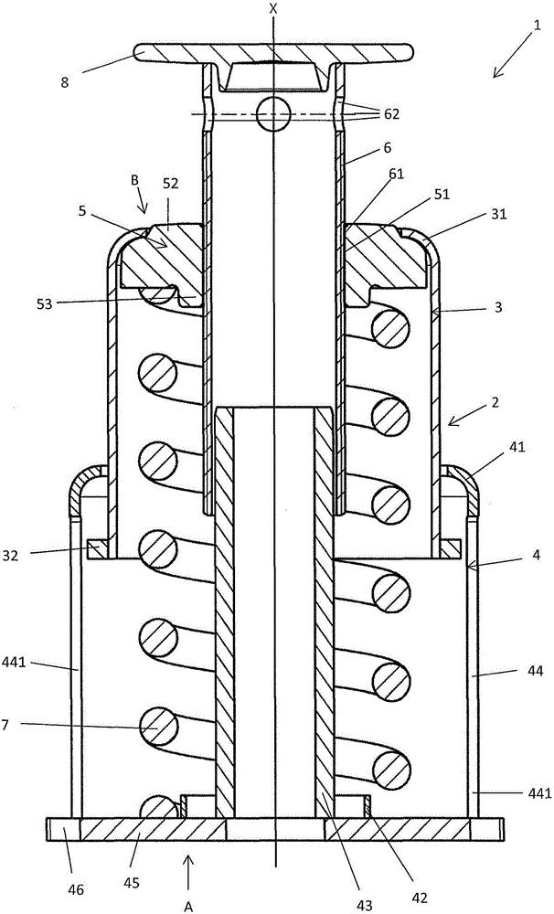
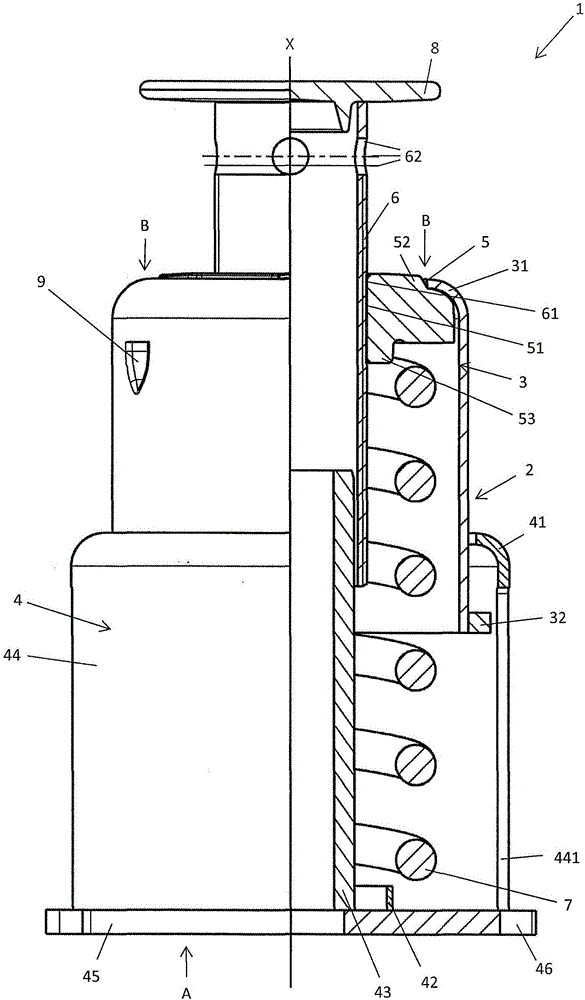
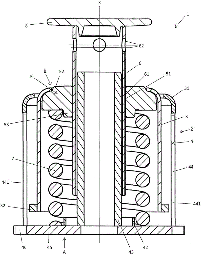
[0034] Figure 1a A schematic sectional view of an embodiment of a spring support device 1 according to the invention is shown. The spring support device 1 comprises a housing 2 consisting of a stationary housing 4 and a movable housing 3 . The resulting two-part construction of the housing 2 can be overall advantageous and particularly simple. The stationary housing is formed in the form of a hollow cylinder. The support side A of the spring support device 1 is arranged on the stationary housing 4 , wherein the spring support device 1 is placed by means of the support side A in its operating position. The stationary housing 4 comprises a base plate 45 provided with holes 46 so that the base plate 45 can be rigidly screwed to ground. The first fixing protrusion 42, the cylindrical guide 43 and the tubular section 44 are welded to the base plate. The tubular section 44 is formed in the manner of a hollow cylinder and has an outer diameter of approximately 200 mm. At its end...


PUM


Abstract

The invention relates to a telescopable spring support (1) which comprises a housing (2), a pressure plate (5), a load pipe (6), and a pressure spring (7) and which is designed to elastically support components in a load direction (X). The housing (2) has a stand side (A) and an upper side (B), and the pressure plate (5) is arranged in the housing (2) and can be moved within the housing (2) in the load direction (X). The pressure spring (7) is arranged between the pressure plate (5) and the stand side (A) and applies a spring force to the pressure plate (5), said spring force being directed towards the upper side (B) in the load direction (X). The load pipe (6) is connected to the pressure plate (5) and, in each position of the pressure plate (5), extends outwards from the interior of the housing (2) through an opening arranged on the upper side (B) of the housing (2). The housing (2) comprises a stand housing (4) and a movable housing (3). The movable housing (3) can be moved towards the stand housing (4) in the load direction (X), wherein the stand housing (4) has a stand side (A), and the movable housing (3) has the opening.

Description

technical field [0001] The invention relates to a telescopic spring support device according to the preamble of claim 1 . Background technique [0002] Conventional spring supports are used in plant engineering or pipeline construction for elastically supporting components in the direction of load. The use of such a spring support is particularly desirable where the load force exerted by the member on the spring support for support varies with conditions and elastic yielding should be provided for said load force. This occurs, for example, when a component is displaced in the load direction due to thermal expansion, for example. These requirements arise especially in pipeline construction when the pipeline has a correspondingly different expansion behavior at different temperatures and thus the expansion of the pipeline leads to displacements in the direction of load. [0003] Conventional spring supports are used in such a way that a component is placed on the spring supp...

Claims


Application Information

Patent Timeline
Patent Type & Authority Applications(China)
IPC IPC(8): F16L3/205
CPCF16L3/2053F16F1/04F16F1/128F16F1/12F16L55/00F16L3/205F16F1/041F16F15/067F16M11/28
Inventor J·贝尔纳特E·海因里希斯A·拉特克
Owner LISEGA SE
Why Eureka
Try Eureka