
A breathing airflow control switch

A technology of airflow control and switching, which is applied in the fields of medical science, prosthesis, and appliances that can be operated by the disabled. It can solve the problems of inconvenience and inability to realize the control of common electrical appliances, and achieve the effect of fast response and light weight

Inactive Publication Date: 2018-02-13
TIANJIN UNIV
View PDF6 Cites 0 Cited by
  • Summary
  • Abstract
  • Description
  • Claims
  • Application Information

AI Technical Summary

Problems solved by technology

[0002] In the hospital, we often see patients who cannot move, or people who cannot move their fingers. When there is no one to take care of them, they cannot control some common electrical appliances, such as the control of electric lights and air conditioners.
It brings great inconvenience to real life

Method used


Image

  • A breathing airflow control switch
  • A breathing airflow control switch
  • A breathing airflow control switch

Examples


Embodiment 1

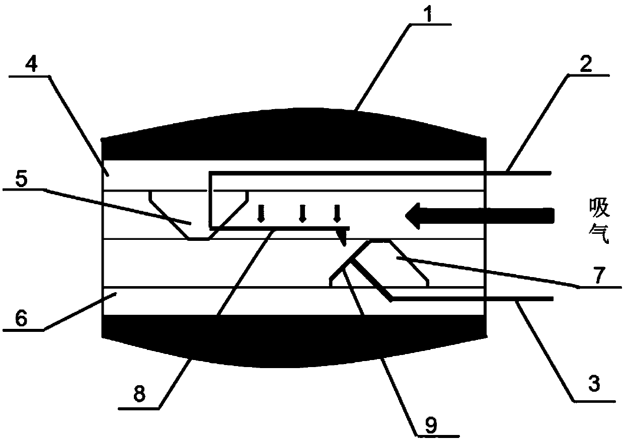
[0027] For this purpose, see figure 1 , the technical solution adopted by the embodiment of the present invention is to use the respiratory airflow pressure to realize the contact and disconnection between the electrodes. The respiratory airflow control switch includes: an elliptical silica gel layer 1, a cuboid with square grooves up and down (upper cuboid 4 and lower cuboid 6), wires embedded in the cuboid (wire 2 embedded in the upper cuboid and lower cuboid The embedded wire 3), the upper and lower triangular bosses (the upper triangular boss 5 and the lower triangular boss 7), the upper triangular boss 5 is provided with an elastic film 8, and the lower triangular boss 7 is provided with a conductive plate 9.

[0028] The elliptical silicone layer 1 fits closely with the nostrils, and its soft surface will not cause damage to the nostrils and has a sealing effect. The shape of the inner hole of the oval silica gel layer 1 is a square hole, which can well wrap up the uppe...

Embodiment 2

[0035] Combine below figure 2 and image 3 The scheme in embodiment 1 is introduced in detail, see the following description for details:

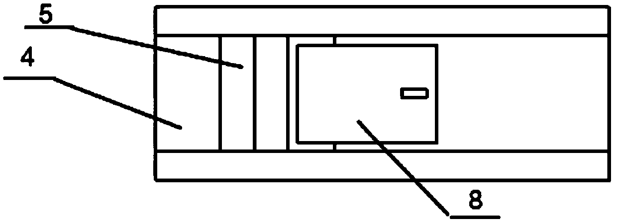
[0036] exist figure 1 Among them, the grooved sides of the upper cuboid 4 and the lower cuboid 6 are bonded to each other, and embedded in the oval silicone layer 1, the positional relationship is as follows figure 2 shown.

[0037] In the upper cuboid 4 and the lower cuboid 6, the upper cuboid embedded wire 2 and the lower cuboid embedded wire 3 are respectively embedded, and a section of them leaks in the air, and the other end extends to the upper triangular boss 5 and the lower triangular boss respectively. The platform 7 is finally connected to the elastic film 8 and the conductive plate 9 respectively.

[0038] exist image 3 Among them, an upper triangular boss 5 is arranged in the square groove of the upper cuboid 4, and an elastic film 8 is suspended on one side thereof. The width of elastic film 8 is slightly smaller than...


PUM


Abstract

The invention discloses a breathing airflow control switch which is an elliptic cylinder in appearance. An outer layer is composed of flexible elliptic silica gel. A main body part is located in a silica gel layer and is composed of an upper layer cuboid and a lower layer cuboid, the middle is provided with a square groove, and triangular bosses are arranged in the groove respectively. One wire is embedded in each cuboid, one end of the wire is suspended in the air, and the other end of the wire is connected with the boss in the corresponding cuboid and connected with an elastic film and a conductive plate respectively through the boss. An air flow cavity is formed in the middle of the two cuboids, and the cavity is divided into an upper cavity and a lower cavity by the boss and the elastic film. A certain distance is reserved between the free end of the elastic film and the lower boss. When a user breathes normally, airflow can pass a slit. When the airflow speed is increased, the pressure below the elastic film is reduced, so that the film is bent downwards, the protruded end of a film end point is in contact with the conductive plate, and the upper wire and the lower wire are connected. The product is quick in reaction speed and light in mass, has no pressure on the nasal cavity, and does not affect normal breath.

Description

technical field [0001] The invention relates to the field of control switches, in particular to a respiratory airflow control switch, which can be used to control various electrical switches. Background technique [0002] In the hospital, we often see patients who cannot move, or people who cannot move their fingers. When there is no one to take care of them, they cannot control some common electrical appliances, such as the control of electric lights and air conditioners. It brings great inconvenience to real life. [0003] The original design intention of the present invention is to achieve the purpose of using the breathing airflow to send out electrical pulse signals, and on this basis, it can further control the surrounding electrical equipment. The main principle is to use the pressure difference of respiratory airflow to realize the action of the conductive film, so as to complete the conduction and electrification of the wire. Contents of the invention [0004] T...

Claims


Application Information

Patent Timeline
Patent Type & Authority Patents(China)
IPC IPC(8): A61F4/00
CPCA61F4/00
Inventor 梁胡格吉乐封皓
Owner TIANJIN UNIV
Learn More