A rubber pad installation mechanism for frame parts

A technology of installation mechanism and frame, which is applied in the field of assembly equipment for parts in the frame, can solve the problems of time-consuming processing, cumbersome operation, and low installation efficiency, and achieve the effects of improving efficiency, convenient operation, and improving the efficiency of material retrieving

Active Publication Date: 2018-11-09
大千纺织(安徽)有限公司
View PDF5 Cites 2 Cited by
  • Summary
  • Abstract
  • Description
  • Claims
  • Application Information

AI Technical Summary

Problems solved by technology

[0003] like figure 2 As shown, the corner of the product 6 in the frame is provided with a rubber pad hole, and the rubber pad needs to be put into the rubber pad hole. Since the rubber pad has the property of elastic deformation, most of the rubber pads are assembled by extrusion , most of the existing rubber pads are installed manually, and a small part has achieved semi-mechanization, but it is still necessary to manually place the product on the processing station, and then press the rubber pad into the rubber pad hole through the extrusion device. The operation is cumbersome, the installation efficiency is low, and a lot of processing time is consumed

Method used


Image

  • A rubber pad installation mechanism for frame parts
  • A rubber pad installation mechanism for frame parts
  • A rubber pad installation mechanism for frame parts

Examples


Embodiment Construction

[0029] In order to enable those skilled in the art to better understand the technical solution of the present invention, the present invention will be described in detail below in conjunction with the accompanying drawings. The description in this part is only exemplary and explanatory, and should not have any limiting effect on the protection scope of the present invention. .

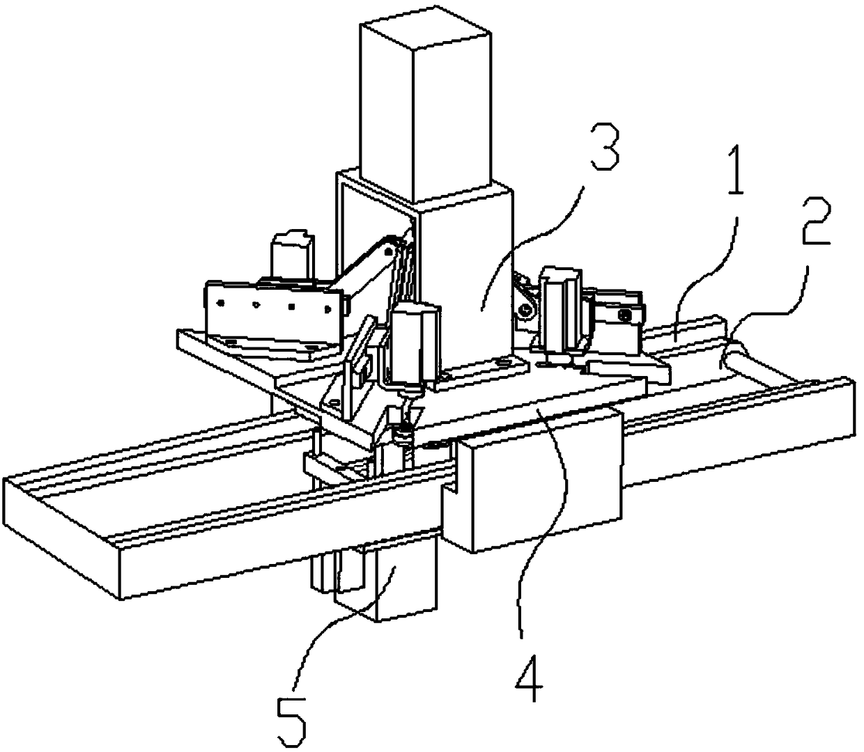
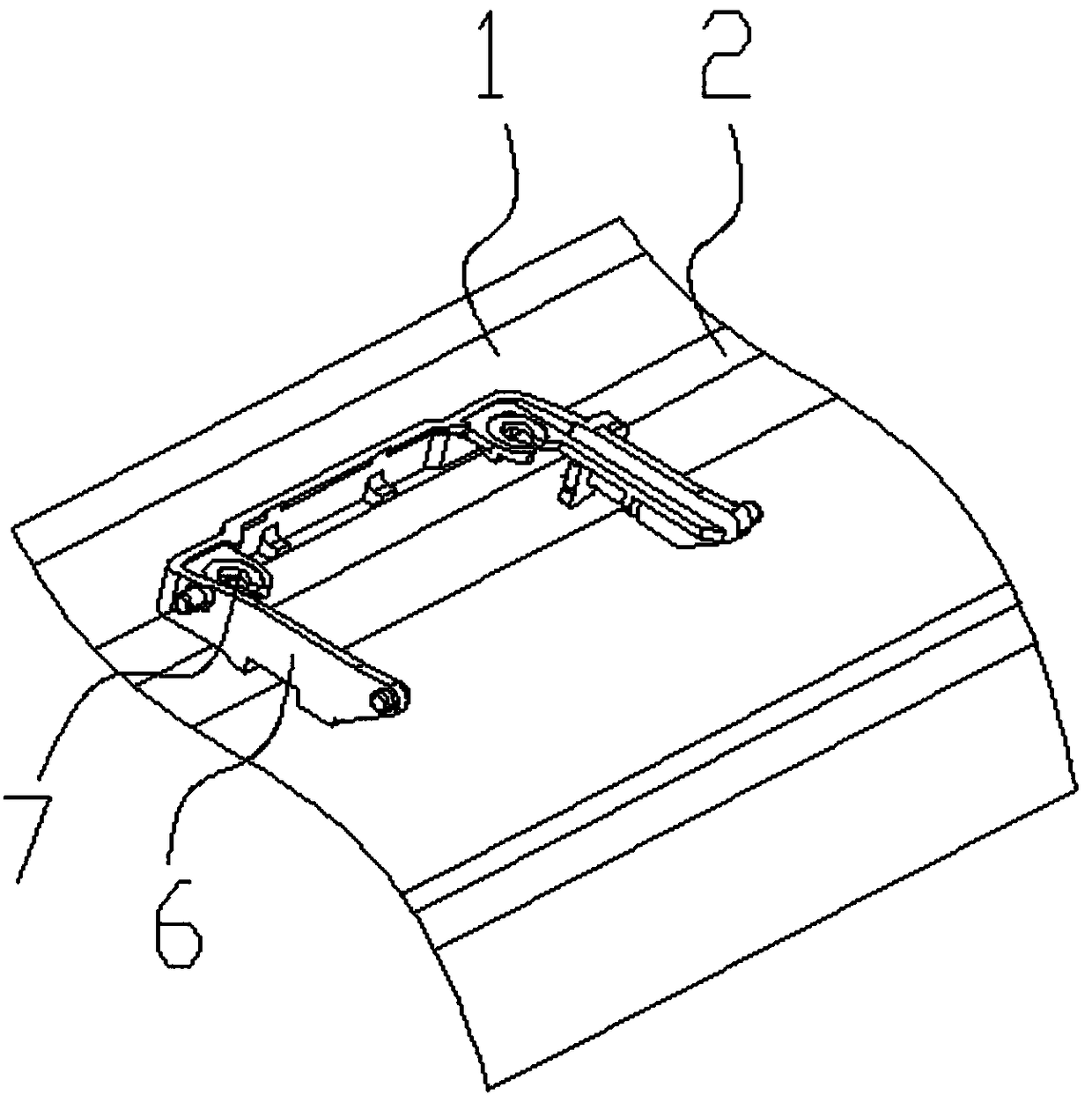
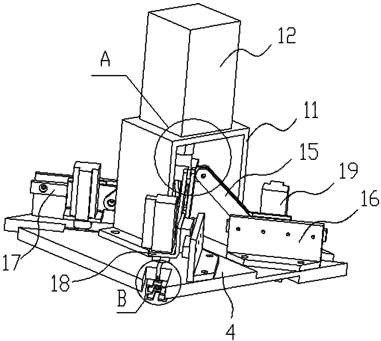
[0030] Such as Figure 1-Figure 5 As shown, the specific structure of the present invention is: a rubber pad installation mechanism for frame parts, which includes a conveyor frame 1, and the conveyor frame 1 is provided with a conveyor belt 2 that cooperates with a product 6, and the horizontal surface of the product 6 The frame sticks to the conveying frame 1, and the conveying frame 1 is provided with a padding device 3 matched with the product, and the described padding device 3 includes a square upper fixing plate 4 arranged above the conveying frame 1, and the described upper fixing The plate 4 ...


PUM


Abstract

The invention relates to a rubber pad mounting mechanism facilitating ejection. The mechanism comprises a conveying frame, a conveying belt matched with a product is arranged on the conveying frame, atransverse frame of the product is attached to the conveying frame, and a pad feeding device matched with the product is arranged on the conveying frame. The pad feeding device comprises a square upper fixing plate above the conveying frame, a material taking groove is formed in the upper fixing plate in the diagonal direction, the material taking groove is matched with a material taking air cylinder, and the material taking air cylinder is connected with a pushing device. An air cylinder head of the material taking air cylinder penetrates through the material taking groove and is matched with a rubber pad. A pushing device and the material taking air cylinder are connected to a controller. The rubber pad mounting mechanism facilitating ejection is provided with the conveying belt matchedwith the product, and a rubber pad feeding device matched with the product is arranged on the conveying belt. The rubber pad is taken and placed through the material taking air cylinder. The rubber pad is pressed in through the pushing device, meanwhile, conveying is not affected, the rubber pad installation efficiency is greatly improved, and the rubber pad installation time is shortened.

Description

technical field [0001] The invention relates to the field of assembly equipment for parts in a frame, in particular to a rubber pad installation mechanism for frame parts. Background technique [0002] In the production process of frame parts, many parts used as support seats need to be added with rubber pads to make them have a certain degree of elasticity and prevent them from being crushed, especially widely used in seat frames. [0003] Such as figure 2 As shown, the corner of the product 6 in the frame is provided with a rubber pad hole, and the rubber pad needs to be put into the rubber pad hole. Since the rubber pad has the property of elastic deformation, most of the rubber pads are assembled by extrusion , most of the existing rubber pads are installed manually, and a small part has achieved semi-mechanization, but it is still necessary to manually place the product on the processing station, and then press the rubber pad into the rubber pad hole through the extrus...

Claims


Application Information

Patent Timeline
Patent Type & Authority Patents(China)
IPC IPC(8): B29C65/64B29C65/78B23P19/027
CPCB23P19/001B23P19/027B29C65/64B29C65/78
Inventor 邓君黄红梅邓凯李培
Owner 大千纺织(安徽)有限公司
Why Eureka
Try Eureka