Variable-gain valve

A variable gain and valve body technology, applied in the field of hydraulic valves, can solve problems such as increased difficulty in installation and adjustment, poor applicability, and increased product complexity, and achieves the effects of convenient use, high reliability, and simple structure

Active Publication Date: 2017-05-17
XIAN AIRCRAFT DESIGN INST OF AVIATION IND OF CHINA
View PDF6 Cites 1 Cited by
  • Summary
  • Abstract
  • Description
  • Claims
  • Application Information

AI Technical Summary

Problems solved by technology

[0003] At present, the realization of variable gain valves is mostly achieved by setting multiple springs with different elastic forces inside the valve. After the hydraulic valve is transferred, the product performance cannot be guaranteed. It needs to be adjusted by adding or reducing gaskets to finally reach the product performance index. Requirements increase the difficulty of installation and adjustment, and poor applicability; in addition, there are higher requirements for mechanical connectors at the input end, which increases the complexity of product installation and use

Method used


Image

  • Variable-gain valve
  • Variable-gain valve
  • Variable-gain valve

Examples


Embodiment Construction

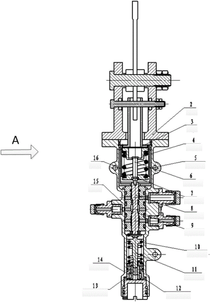
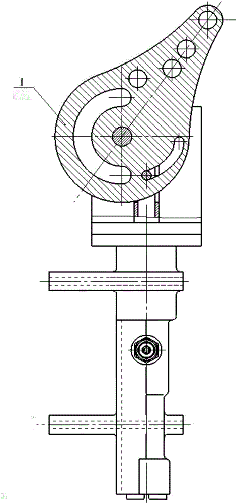
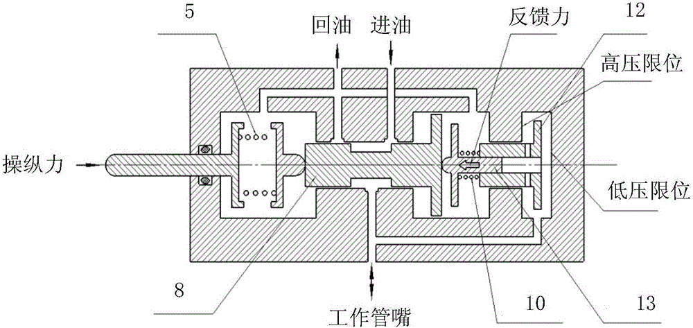
[0020] like figure 1 and 2 As shown, a variable gain valve is characterized in that: the gain valve includes a cam 1, a bracket 2, a sleeve 3, a spring seat 4, a decompression spring 5, a push rod 6, a valve body, a feedback spring 10, a feedback Rod 11, large feedback piston 12 and small feedback piston 13;

[0021] On one side of the valve body: the cam 1 is installed on the bracket 2 through the rotating shaft, and the cam 1 is provided with an arc-shaped surface, and the arc-shaped surface includes a variable-diameter arc-shaped surface segment and an equal-diameter arc-shaped surface segment. The contour line of the variable-diameter arc surface segment has the same center, and the distance between the contour line of the surface and the center of the circle increases gradually. The contour line of the surface segment is the same circle center, and one end of the connecting rod on the sleeve 3 is in contact with the arc surface;

[0022] The spring seat 4 and the decom...


PUM


Abstract

The invention belongs to aerial hydraulic technologies and relates to a variable-gain valve. The variable-gain valve comprises a cam, a support, a sleeve, an ejector rod, a pressure relief spring assembly, a sliding valve assembly, a feedback piston assembly, a feedback spring and the like. The variable-gain function is achieved by arranging a large feedback piston and a small feedback piston inside the valve. The pressure retaining function of the input displacement tail section is achieved by utilizing the cam as a displacement input interface device. The variable-gain valve is simple in structure, convenient to use and high in reliability, and can be widely applied to hydraulic valves with the variable-gain requirement for output pressure and input displacement in the military and civil fields.

Description

technical field [0001] The invention relates to a hydraulic valve, in particular to a variable gain valve. Background technique [0002] In the field of aviation hydraulics, it involves the use of a variable gain valve. Due to practical work requirements, the linear relationship between output pressure and input displacement is required to be segmented, that is, in the front section of the displacement input, the output pressure is a certain value for the input displacement. A gain; in the middle of the displacement input, the output pressure is another gain for the input displacement; in the end of the displacement input, the output pressure remains unchanged. [0003] At present, the realization of the variable gain valve is mostly realized by setting multiple springs with different elastic forces inside the valve. After the hydraulic valve transfer is completed, the product performance cannot be guaranteed. It needs to be adjusted by adding or reducing gaskets to finally ...

Claims


Application Information

Patent Timeline
Patent Type & Authority Applications(China)
IPC IPC(8): F15B13/02
CPCF15B13/02
Inventor 李欣王子瑾刘泽华谢彦
Owner XIAN AIRCRAFT DESIGN INST OF AVIATION IND OF CHINA
Why Eureka
Try Eureka