Test beam long-term loading system and method

A loading system and test beam technology, applied in the direction of elasticity testing, machine/structural component testing, measuring devices, etc., can solve the problems of a large number of high-density loading blocks, difficult to meet the loading level, inconvenient loading and unloading, etc. and unloading, saving time and effort, convenient processing, and convenient operation.

Inactive Publication Date: 2017-05-17
RES INST OF HIGHWAY MINIST OF TRANSPORT
View PDF5 Cites 12 Cited by
  • Summary
  • Abstract
  • Description
  • Claims
  • Application Information

AI Technical Summary

Problems solved by technology

For components with a large model size, the mechanical response needs to meet the test requirements. Generally, a large load needs to be applied to achieve the goal of the research. If surcharge loading is used, a large number of high-density loading blocks are required, and the cost is high. , inconvenient to add and unload
If a small jack is used to load the ground anchor and the reaction frame, it is difficult to meet the requirements of the loading level

Method used


Image

  • Test beam long-term loading system and method
  • Test beam long-term loading system and method
  • Test beam long-term loading system and method

Examples


Embodiment 1

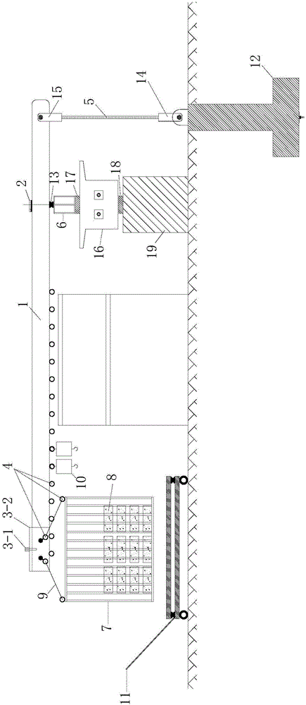
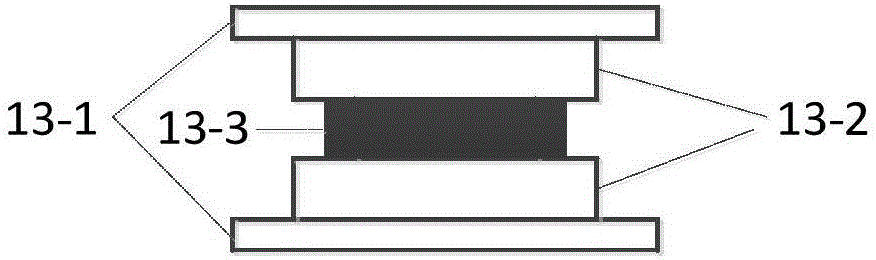
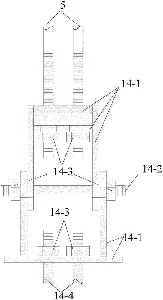
[0054] The long-term loading system of the test beam as figure 1 , 2 , 3, and 4, including lever 1, level pipe 2, free sliding device 3 (locating bolt 3-1, sliding steel channel 3-2), lifting ring 4, tension rod 5, distribution beam 6, hanging basket 7, and accessories Weight 8, lifting rope 9, manual hydraulic weight adjustment device 11, ground anchor 12, force transmission and testing device 13 (13-1 is the upper and lower backing plate, 13-2 is the customized steel ring, 13-3 is the pressure sensor), Connector 14 (14-1 is a welded steel plate, 14-2 is a high-strength screw, 14-3 is a high-strength bolt nut, and 14-4 is a ground anchor screw) for connecting the tension rod and the ground anchor. Lever connection regulator 15 (15-1 is welded steel plate, 15-2 is high-strength screw rod, 15-3 is high-strength bolt and nut), test beam 16, force distribution loading point backing plate 17, test beam support 18, test beam Pedestal 19. The specific assembly is mainly completed...

Embodiment 2

[0069] The long-term loading system of the test beam as figure 1 , 2 , shown in 3 and 4, including lever 1, level pipe 2, suspension ring 4, tension rod 5, distribution beam 6, weight 10, ground anchor 12, force transmission and testing device 13 (13-1 is backing plate up and down, 13 -2 is a customized steel ring, 13-3 is a pressure sensor), a connector 14 for connecting the tension rod and the ground anchor (14-1 is a welded steel plate, 14-2 is a high-strength screw rod, 14-3 is a high-strength bolt and nut, 14-4 is the ground anchor screw), the connection regulator 15 (15-1 is the welded steel plate, 15-2 is the high-strength screw, 15-3 is the high-strength bolt and nut) used to connect the tension bar and the lever, the test beam 16, the force Distribute the loading point backing plate 17, the test beam support 18, and the test beam pedestal 19. The specific assembly is mainly completed by the following steps:

[0070] (1) First, according to the design drawing of the...


PUM


Abstract

The invention discloses a test beam long-term loading system and method. The loading system comprises a lever, a tension bar, a distributive beam, a counterweight device, a hydraulic pressure weight adjusting device, a ground anchor and a force transmission and testing device; the design of a loading system is carried out using the lever principle, firstly based on the test requirements, the size of the applied load as required is set; after the determination of the size of the load, the length ratio of the short arm and the long arm of the lever is designed from the size of the test site, the size of the loading lever and other aspects, under the precondition that the weight of the lever is not taken into consideration; in theory, the larger is the length ratio of the short arm and the long arm of the lever, the larger is the weight applied to the force bearing point of the long arm, and the larger is the amplifying multiple of the load at the force bearing point of the lever, and the aim of applying relatively large load is further achieved by utilizing relatively small weight. The long-term loading system is easy to operate, the loading and unloading save time and labor, the performance is stable, and long-term testing is guaranteed. The long-term loading system in the later period does not require special maintenance, and basically is not affected by external conditions.

Description

technical field [0001] The invention relates to the field of bridge structure test loading, in particular to a long-term loading system and method for test beams. Background technique [0002] In the basic technology research and engineering application research of bridge structures, in order to obtain the characteristics of the mechanical indicators of certain structures or components, the real bridge structural components are often used as prototypes, and the model is made according to the similarity theory as the research object, and then the mechanical performance test is carried out. Simulate the response of structural members under loading and stress. Therefore, choosing the appropriate loading method and loading equipment is the key to ensure the smooth progress of the whole test work. [0003] General structural laboratories are equipped with pressure testing machines and reaction frames with a certain load tonnage, which are applied to short-term mechanical perform...

Claims


Application Information

Patent Timeline
Patent Type & Authority Applications(China)
IPC IPC(8): G01M5/00
CPCG01M5/0008G01M5/0075
Inventor 宋建永徐强李明
Owner RES INST OF HIGHWAY MINIST OF TRANSPORT
Why Eureka
Try Eureka