
SMT (surface mount technology) device detection method and system

A detection method and detection system technology, applied in the direction of instruments, measuring devices, scientific instruments, etc., can solve problems such as inconvenient positioning and detection obstacles, and achieve the effect of improving detection effect and efficiency, reducing labor, and clear and unobstructed images

Pending Publication Date: 2017-05-17
SHENZHEN BLUIRIS TECH CO LTD
View PDF7 Cites 0 Cited by
  • Summary
  • Abstract
  • Description
  • Claims
  • Application Information

AI Technical Summary

Problems solved by technology

[0003] However, since the target component is only a small part of the software interface, it is inconvenient to locate, and it is easily blocked by other display content, such as a cross or other images to locate the target component, causing detection obstacles

Method used


Image

  • SMT (surface mount technology) device detection method and system
  • SMT (surface mount technology) device detection method and system
  • SMT (surface mount technology) device detection method and system

Examples


Embodiment Construction

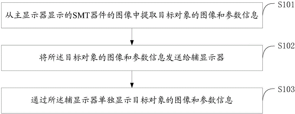
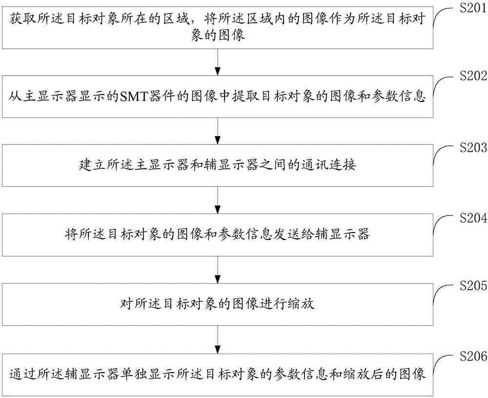
[0018] see figure 1 , figure 1 It is a method flowchart of the SMT device detection method in an embodiment.

[0019] In this embodiment, the SMT device detection method includes:

[0020] S101. Extract the image and parameter information of the target object from the image of the SMT device displayed on the main display.

[0021] The chip electronic components are welded on the printed circuit board through SMT technology to obtain SMT devices, which are PCB boards obtained through SMT technology. SMT devices need to be inspected before leaving the factory. The first part refers to a certain number sample.

[0022] Obtain the image of the SIM device and display it on the main monitor, select the electronic component to be detected as the target object, and extract the image and parameter information of the target object, the parameter information includes the model, size, parameters, etc. of the target object.

[0023] S102. Send the image and parameter information of the...


PUM


Abstract

The invention relates to an SMT (surface mount technology) device detection method and system. The SMT device detection method comprises the steps of extracting an image and parameter information of a target object from an image of an SMT device displayed by a primary display, transmitting the image and the parameter information of the target object to an auxiliary display and individually displaying the image and the parameter information of the target object through the auxiliary display; and extracting the image of the target object from the image of the SMT device. Through displaying of the individually arranged display, individual displaying of a target device can be achieved, the image is clear and uncovered, the labor of a detector is reduced and the detection effect and efficiency are improved.

Description

technical field [0001] The invention relates to the field of SMT device detection, in particular to a SMT device detection method and system. Background technique [0002] At present, in the SMT (Surface Mount Technology, surface mount technology) device inspection system, the target components of the test are framed by crosses or some graphics to facilitate the user's rapid positioning, and the target components are displayed on the entire software interface small portion. This method has great advantages over the traditional visual object method. It can assist the inspector to quickly locate the target component through image magnification and marking, and then quickly perform corresponding detection on the component. [0003] However, since the target component is only a small part of the software interface, it is inconvenient to locate, and it is easily blocked by other display content, such as a cross or other images for positioning the target component, causing detect...

Claims


Application Information

Patent Timeline
Patent Type & Authority Applications(China)
IPC IPC(8): G01N21/84G01B11/00
CPCG01B11/00G01N21/84
Inventor 梁建勇解孝文叶再惠易云
Owner SHENZHEN BLUIRIS TECH CO LTD
Learn More