
Sound wave temperature-measuring sounding device and receiving device

A technology of a sounding device and a receiving device, which is applied in the direction of analyzing fluids, analyzing materials, and instruments using sound waves/ultrasonic waves/infrasonic waves, which can solve problems such as large measurement errors, inconvenient maintenance, and short service life, and achieve simple structure and accurate measurement High-strength, small-volume effect

Active Publication Date: 2017-05-17
EASTERN BOILER CONTROL CO LTD
View PDF12 Cites 0 Cited by
  • Summary
  • Abstract
  • Description
  • Claims
  • Application Information

AI Technical Summary

Problems solved by technology

[0004] The purpose of the present invention is to provide a sound wave temperature measuring device and a receiving device to solve the problems of large measurement error, short service life and inconvenient maintenance of the existing furnace sound wave temperature measuring device

Method used


Image

  • Sound wave temperature-measuring sounding device and receiving device
  • Sound wave temperature-measuring sounding device and receiving device
  • Sound wave temperature-measuring sounding device and receiving device

Examples


Embodiment Construction

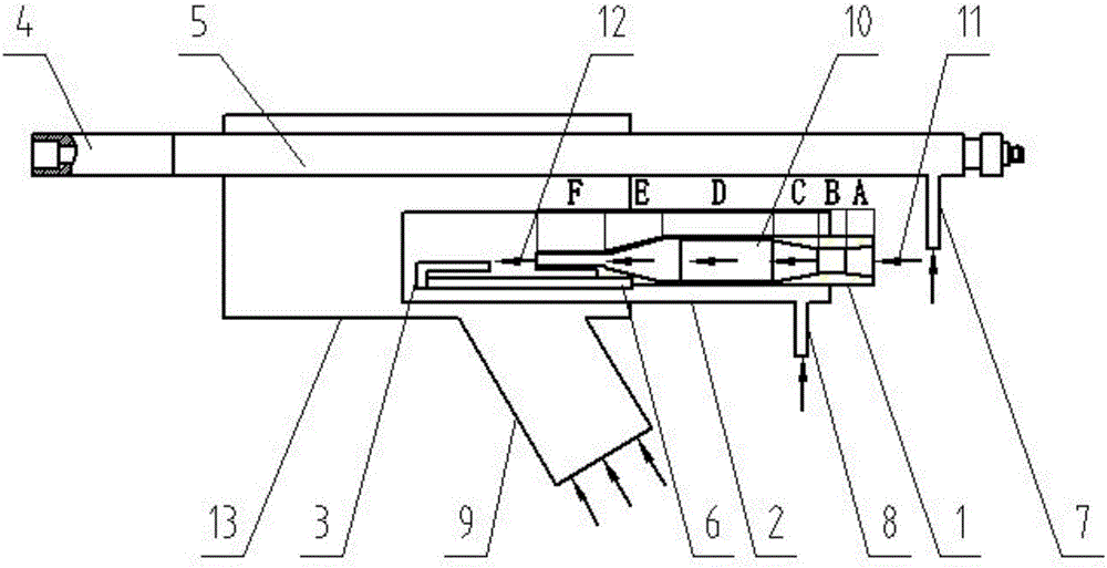
[0019] Examples such as figure 1 As shown, an acoustic temperature measurement and sounding device includes a mounting assembly 13 and a sounding cavity 2 arranged on the mounting assembly 13, and the sounding cavity 2 is a cylindrical structure. The sounding cavity 2 is fixedly provided with a nozzle 1 , the inlet end of the nozzle 1 extends out of the sounding cavity 2 , and the gas outlet end of the nozzle 1 is placed in the sounding cavity 2 . The nozzle 1 is arranged eccentrically in the sound emitting cavity 2 . A reed 3 is also provided in the sound emitting cavity 2 . The reed 3 is a cantilever structure with one end fixed. The end of the reed 3 is arranged opposite to the gas outlet end of the nozzle 1 . The reed 3 is fixed on the outer wall of the nozzle 1 through the connecting plate 6, the end of the reed 3 away from the nozzle 1 is connected to the connecting plate 6, and the end close to the nozzle 1 is a free end. The distance between the nozzle 1 and the reed...


PUM


Abstract

The invention discloses a sound wave temperature-measuring sounding device and a receiving device. The sound wave temperature-measuring sounding device comprises a sounding chamber and a nozzle arranged in the sounding chamber, wherein an air inlet end of the nozzle extends out of the sounding chamber; a reed is arranged in the sounding chamber; the reed has a cantilever structure with one end being fixed; and the tail end of the reed is opposite to an air outlet end of the nozzle. A sound wave temperature-measuring receiving device comprises at least one receiving tube front section and one receiving tube rear section, wherein the receiving tube front section and the receiving tube rear section both have a drum-shaped structure. According to the invention, the nozzle, the reed and the sounding chamber are cooperated for generating a high-decibel and high-frequency sound source, and then the receiving device is used for receiving the temperature for monitoring a boiler furnace; the device has the advantages of simple structure, low failure rate and high measurement accuracy; and the device can be widely applied to the field of temperature measurement of the high temperature furnace.

Description

technical field [0001] The invention relates to the field of boiler furnace temperature measurement, in particular to an acoustic temperature measurement and sound emitting device and a receiving device. Background technique [0002] The principle of furnace acoustic temperature measurement is mainly to solve the temperature field by using the speed change caused by the action of sound wave in the gas medium and the gas temperature. There are two types of traditional furnace temperature measurement devices: contact type and non-contact type: contact type belongs to the traditional measurement method, such as telescopic thermometer, the probe penetrates into the furnace for a long time, is heavy, easily deformed and jammed, has a high failure rate, and cannot be continuously When put into use, the measured temperature is discontinuous. The furnace wall measurement is only for the water wall. These traditional measurement methods are difficult to truly reflect the temperatur...

Claims


Application Information

Patent Timeline
Patent Type & Authority Applications(China)
IPC IPC(8): G01N29/02
CPCG01N29/02G01N2291/021
Inventor 伍建平武飞杨庆峰刘彦涛马祥马晓刚
Owner EASTERN BOILER CONTROL CO LTD
Learn More