
Projector and wavelength conversion device

A wavelength conversion device and wavelength conversion technology, applied in the field of projectors, can solve problems such as detachment, insufficient phosphor wheel assembly strength, and affect product quality, and achieve the effect of improving reliability

Active Publication Date: 2017-05-17
CORETRONIC
View PDF4 Cites 15 Cited by
  • Summary
  • Abstract
  • Description
  • Claims
  • Application Information

AI Technical Summary

Problems solved by technology

[0003] Since the phosphor wheel is driven by the drive motor, the rotation speed is quite high. If the dynamic balance of the phosphor wheel cannot be ensured, it is easy to generate noise, which will affect the quality of the product and even cause damage to the phosphor wheel.
In addition, phosphor wheels are often detached during high-speed rotation due to insufficient assembly strength. Therefore, how to improve the above problems has become the focus of attention of relevant personnel in the field.

Method used


Image

  • Projector and wavelength conversion device
  • Projector and wavelength conversion device
  • Projector and wavelength conversion device

Examples


Embodiment Construction

[0025] The foregoing and other technical contents, features and effects of the present invention will be clearly presented in the following detailed description of a preferred embodiment with reference to the accompanying drawings. The directional terms mentioned in the following embodiments, such as: up, down, left, right, front or back, etc., are only referring to the directions of the drawings. Accordingly, the directional terms are used to illustrate and not to limit the invention.

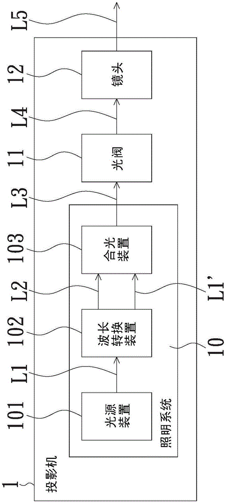
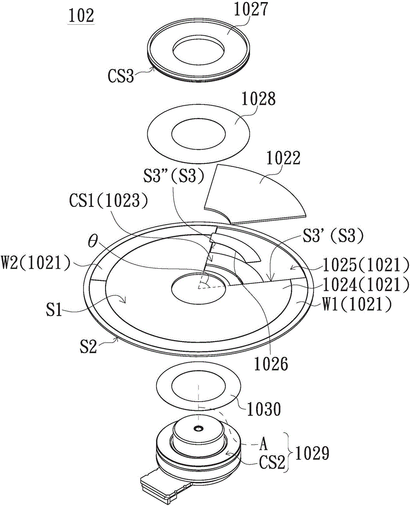
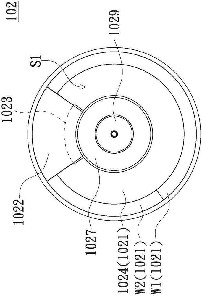
[0026] figure 1 It is a functional block diagram of a projector according to an embodiment of the present invention. figure 2 It is an exploded diagram of components of a wavelength conversion device according to an embodiment of the present invention. image 3 for figure 2 A schematic top view of the assembled wavelength conversion device shown. Figure 4 for figure 2 A schematic bottom view of the assembled wavelength conversion device shown. Such as Figure 1 to Figure 4 As shown,...


PUM


Abstract

A projector includes an illumination system having light source device and wavelength conversion device. The light source device provides a first beam. The wavelength conversion device includes wavelength conversion element, light transmissive element, and weighting structure. The wavelength conversion element includes substrate, at least one wavelength conversion region, and through slot. The at least one wavelength conversion region is disposed on the substrate and converts a portion of the first beam into a second beam. The light transmissive element is disposed at the through slot to form a light transmissive region. The remaining portion of the first beam passes through the light transmissive region, and an illumination light beam is constituted by the second beam and the remaining portion of the first beam. The weighting structure is connected to the substrate and has a first joint surface, and the first joint surface and the light transmissive element are jointed. The weighting structure can increase connection area during assemblement of the componenets, thus improving the reliability of the structure.

Description

technical field [0001] The present invention relates to a projector, in particular to a projector with a wavelength conversion device. Background technique [0002] In the current laser projection device, the principle is to use the good luminous efficiency of the laser diode to excite the phosphor to generate the pure color light source required by the projector. Generally, phosphor powder is coated on a substrate to form a phosphor wheel, and then the phosphor powder on the substrate is excited by a laser beam emitted by a laser light source to generate light of different colors. In addition, the laser can also pass through the phosphor wheel directly through the hollow slots on the substrate. The phosphor wheel is driven by the driving motor to rotate, so that the phosphor powder coated on the substrate representing different color areas corresponds to the laser beam emitted by the laser light source, thereby generating corresponding colored light. [0003] Since the ph...

Claims


Application Information

Patent Timeline
Patent Type & Authority Applications(China)
IPC IPC(8): G03B21/20
CPCG03B21/204H04N9/3158G02B26/008H04N9/3111
Inventor 徐碧聪
Owner CORETRONIC
Learn More