System model correction method oriented to multipoint excited vibration test
A technology for exciting vibration and system models, applied in special data processing applications, instruments, electrical and digital data processing, etc., can solve the problems that the modal cannot be excited, increase the test cost, and limit the number of test degrees of freedom.
- Summary
- Abstract
- Description
- Claims
- Application Information
AI Technical Summary
Problems solved by technology
Method used
Image


Examples
Embodiment Construction
[0045] In order to make the object, technical solution and advantages of the present invention more clear, the present invention will be further described in detail below in conjunction with the examples. It should be understood that the specific embodiments described here are only used to explain the present invention, not to limit the present invention.
[0046] The application principle of the present invention will be described in detail below in conjunction with the accompanying drawings.
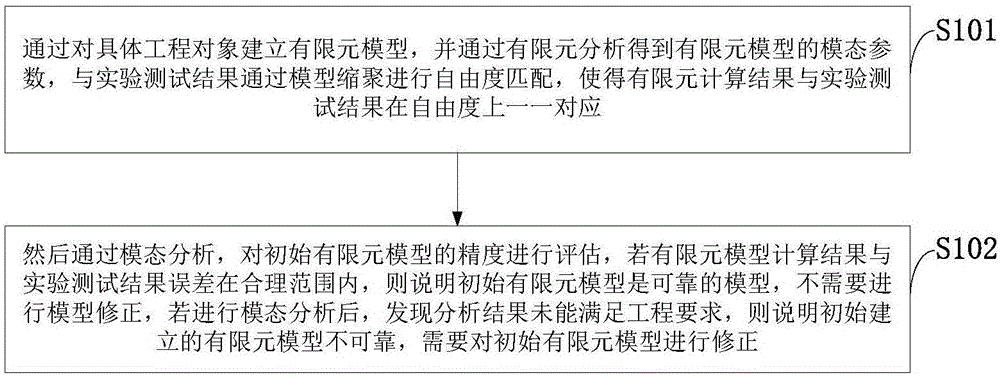
[0047] like figure 1 As shown, the system model correction method for the multi-point excitation vibration test provided by the embodiment of the present invention includes the following steps:
[0048] S101: By establishing a finite element model for a specific engineering object, and obtaining the modal parameters of the finite element model through finite element analysis, the degrees of freedom are matched with the experimental test results through model condensation, so that the ...
PUM
 Abstract
Description
Claims
Application Information
 - Generate Ideas
- Intellectual Property
- Life Sciences
- Materials
- Tech Scout
- Unparalleled Data Quality
- Higher Quality Content
- 60% Fewer Hallucinations
Browse by: Latest US Patents, China's latest patents, Technical Efficacy Thesaurus, Application Domain, Technology Topic, Popular Technical Reports.
© 2025 PatSnap. All rights reserved.Legal|Privacy policy|Modern Slavery Act Transparency Statement|Sitemap|About US| Contact US: help@patsnap.com