Supercharge Your Innovation With Domain-Expert AI Agents!

Synchronous transmission device of cylindrical inductor base

A conveying device and cylindrical technology, which is applied in the field of cylindrical inductive base synchronous conveying device, can solve the problems of high labor cost, many subjective factors, and many manpower of electronic connection base, etc., and achieve the effect of high conveying efficiency and precise conveying.

Inactive Publication Date: 2017-05-17
SUZHOU PIN SHINE TECH
View PDF8 Cites 4 Cited by
  • Summary
  • Abstract
  • Description
  • Claims
  • Application Information

AI Technical Summary

Problems solved by technology

For the insertion of the pins, the most traditional way is to manually insert the pins into the round holes one by one, and then insert the pins into the whole board with the help of a simple plate mold. The speed has been improved to a certain extent, but it still needs to be completed by hand using molds. For mass-produced electronic connectors, it still requires more manpower to complete, and the labor cost is extremely high; and it is completed manually, with many subjective factors. Quality and precision are difficult to guarantee, so in today's emphasis on efficiency and quality, this manual method of using molds for pin insertion is becoming less and less suitable for the needs of market development.

Method used


Image

  • Synchronous transmission device of cylindrical inductor base
  • Synchronous transmission device of cylindrical inductor base
  • Synchronous transmission device of cylindrical inductor base

Examples


Embodiment Construction

[0016] The present invention will be further described below in conjunction with the embodiments shown in the accompanying drawings.

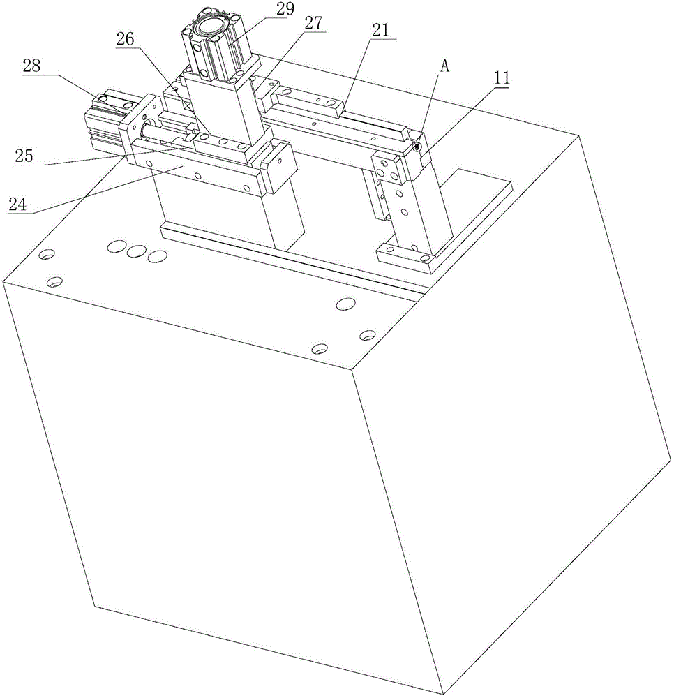
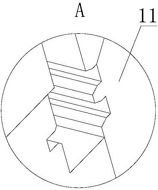
[0017] Such as figure 1 , 2 As shown, the cylindrical inductive base synchronous conveying device includes a conveying channel 11 with an open upper end, and a conveying plate whose lower end is inserted in the conveying channel 11 and can slide up / down / left / right in the conveying channel 11 21. A driving part that drives the conveying plate 21 to slide up / down / left / right, and a counter for checking whether pins are missing.

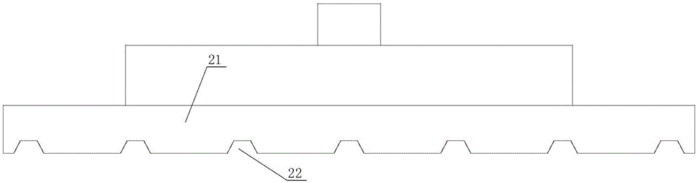
[0018] Such as figure 2 , 3 As shown in , 4, the length direction of the conveying channel 11 is the left-right direction, and the width direction is the front-to-rear direction, and the lower end surface of the conveying plate 21 is provided with a conveying groove 22 that runs through the front and rear end faces of the conveying channel for the seat body or the base of the base, The rear side wall of the delivery ...


PUM


Abstract

The invention discloses a synchronous transmission device of a cylindrical inductor base. The synchronous transmission device comprises a transmission passage, a transmission plate and a driving part, wherein an upper end of the transmission passage is opened, a lower end of the transmission plate is inserted into the transmission passage, the transmission plate can slide in the transmission passage upwards / downwards / leftwards / rightwards, the driving part is used for driving the transmission plate to slide upwards / downwards / leftwards / rightwards, the length direction of the transmission passage is a horizontal direction, the width direction of the transmission passage is a vertical direction, a transmission groove is formed in a lower end surface of the transmission plate, penetrates through a front end surface and a rear end surface of the transmission plate and is used for transmitting a seat body of the base and the base, a rear limitation groove is formed in a rear side wall of the transmission passage and is matched with a bulge on a rear end surface of the seat body, and a front limitation groove is formed in a front side wall of the transmission passage and is matched with a bulge on a front end surface of the seat body. The seat body and the base assembled in advance are synchronously transmitted by the transmission plate and the transmission passage, and the synchronous transmission device is high in transmission efficiency and accurate in transmission.

Description

technical field [0001] The invention relates to production equipment for inductance bases, in particular to a synchronous conveying device for cylindrical inductance bases. Background technique [0002] Today, with the popularity and rapid development of electronic products, the demand for electronic connectors inside electronic products is also increasing. The socket of the electronic connector is molded by plastic injection, and a plurality of circular holes for inserting pins are arranged on the main body of the socket. For the insertion of the pins, the most traditional way is to manually insert the pins into the round holes one by one, and then insert the pins into the whole board with the help of a simple plate mold. The speed has been improved to a certain extent, but it still needs to be completed by hand using molds. For mass-produced electronic connectors, it still requires more manpower to complete, and the labor cost is extremely high; and it is completed manual...

Claims


Application Information

Patent Timeline
IPC IPC(8): H01R43/00H01R43/20
CPCH01R43/00H01R43/20
Inventor 王千群刘建刚
Owner SUZHOU PIN SHINE TECH
Features
  • R&D
  • Intellectual Property
  • Life Sciences
  • Materials
  • Tech Scout
  • Unparalleled Data Quality
  • Higher Quality Content
  • 60% Fewer Hallucinations
Learn More