
A multiplexing device of NFC coil and wireless charging coil

A wireless charging and multiplexing device technology, which is applied in circuit devices, battery circuit devices, transportation and packaging, etc., can solve the problem of unavoidable close contact between NFC coils and wireless charging coils, poor isolation between NFC and wireless charging coils, and signal problems. Problems such as large crosstalk

Inactive Publication Date: 2019-03-26
SHANGHAI AMPHENOL AIRWAVE COMM ELECTRONICS CO LTD
View PDF4 Cites 0 Cited by
  • Summary
  • Abstract
  • Description
  • Claims
  • Application Information

AI Technical Summary

Problems solved by technology

[0003] However, although NFC and wireless charging reuse the same piece of ferrite electromagnetic shielding material, the coil and circuit exist independently, which will cause a problem: when the given occupied area is certain, the NFC coil and wireless charging coil often need Compromise on area and isolation leads to deterioration of both NFC coil performance and wireless charging coil performance. At the same time, NFC coil and wireless charging coil are inevitably in close contact, and mutual interference cannot be effectively eliminated in a small space. Therefore, , the industry has proposed the idea of ​​sharing a coil with NFC and wireless charging
[0004] At present, NFC and wireless charging coils realize time-sharing multiplexing of NFC and wireless charging coils in the form of electronic switches. However, the implementation of electronic switches has the following disadvantages: 1. Electronic switches generally cannot withstand high power, and wireless charging of smart terminals The power is as high as 10W or more, and the requirement for charging power is getting higher and higher. It is necessary to develop an electronic switch with a higher rated power; Large crosstalk; 3. The introduction of electronic switches will inevitably lead to a drop in efficiency, which will be converted into excess heat, which poses a challenge to the heat treatment of mobile terminals

Method used


Image

  • A multiplexing device of NFC coil and wireless charging coil
  • A multiplexing device of NFC coil and wireless charging coil
  • A multiplexing device of NFC coil and wireless charging coil

Examples


Embodiment Construction

[0036] The present invention will be further described in detail below through specific embodiments in conjunction with the accompanying drawings.

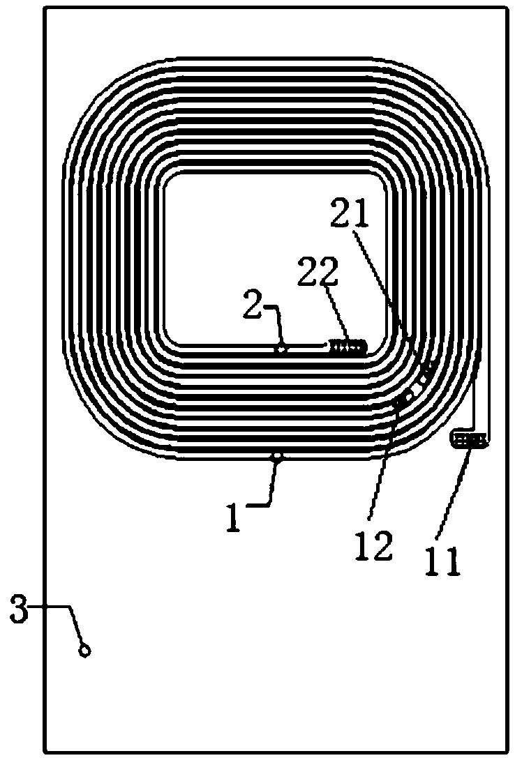
[0037] This example provides a multiplexing device for NFC coils and wireless charging coils, including a first coil 1, a second coil 2, a carrier 3, a metal line 4, an NFC circuit 5, a wireless charging circuit 6, a control circuit 7, and a magnetic switch Mechanism 8 and ferrite electromagnetic shielding film 9.

[0038] Such as figure 1 As shown, the first coil 1 and the second coil 2 are arranged on the front of the carrier 3, specifically, the second coil 2 is spirally arranged on the carrier 3, the first coil 1 is spirally arranged outside the second coil 2, and the second The tail end 12 of the first coil 1 is not connected to the head end 21 of the second coil 2, wherein the first coil 1 is designed and manufactured to meet the NFC function, so that the first coil 1 and the NFC circuit 5 are connected to form a loop to re...


PUM


Abstract

The invention relates to a multiplex device of a near field communication (NFC) coil and a wireless charging coil. The multiplex device comprises a first coil, a second coil, a carrier, a metal circuit, an NFC circuit, a wireless charging circuit, a control circuit and a magnetic switching mechanism; during wireless charging, the magnetic switching mechanism is used for combining the first coil and the second coil to form a charging coil according to a current provided by the control circuit, communicating with the wireless charging circuit to form a wireless charging loop and simultaneously cutting off the NFC circuit; and during NFC, the magnetic switching mechanism is used for disconnecting the first coil and the second coil according to the current provided by the control circuit, disconnecting the wireless charging circuit and enabling the first coil and the NFC circuit to form an NFC loop. A current signal is used for controlling the magnetic switching mechanism so as to achieve switching between wireless charging and NFC, the magnetic switching mechanism can be used for thoroughly cutting off the wireless charging loop and the NFC loop, and no efficiency loss is generated; and meanwhile, the NFC circuit is disconnected during wireless charging, the wireless charging circuit is disconnected during NFC, and no signal interference exists between the NFC circuit and the wireless charging circuit.

Description

technical field [0001] The invention relates to the technical fields of NFC and wireless charging, in particular to a multiplexing device of an NFC coil and a wireless charging coil. Background technique [0002] The full name of NFC is Near Field Communication, that is, near-field communication, which is derived from radio frequency identification (RFID, Radio Frequency ldentify Detection) technology. Point-to-point short-range communication between various devices. NFC technology is widely used in wireless payment, data transmission and other fields. In recent years, as mobile payment has become more and more popular in life, NFC has gradually become the standard configuration of smartphones. At the same time, the long-silent wireless charging technology has The charging power has been significantly improved, and the space and resources occupied by NFC can be partially reused, and it has begun to gradually integrate with NFC. [0003] However, although NFC and wireless c...

Claims


Application Information

Patent Timeline
Patent Type & Authority Patents(China)
IPC IPC(8): H02J50/10H02J7/00H04B5/00H01F38/14H01F27/40
CPCH01F27/40H01F38/14H01F2038/143H02J7/025H04B5/0093
Inventor 何大伟满方明
Owner SHANGHAI AMPHENOL AIRWAVE COMM ELECTRONICS CO LTD
Learn More