
Shredding device for maize harvesting machine impurity removal draught fan

A technology of corn harvester and chopping device, which is applied in the direction of harvesters, agricultural machinery and implements, cutters, etc., which can solve the problems of large impurity particles discharged, increased load of peeling machines, and blockage of impurity exhaust fans, etc., and achieve fine particle size , Improve the efficiency and reliability of use, and facilitate the use of the effect

Inactive Publication Date: 2017-05-24
YONGMENG MACHINERY CO LTD
View PDF0 Cites 2 Cited by
  • Summary
  • Abstract
  • Description
  • Claims
  • Application Information

AI Technical Summary

Problems solved by technology

[0002] At present, the miscellaneous fan device is mainly used in corn harvester equipment. Usually, the miscellaneous fan device in the corn harvester adopts the rotating blade type without a chopping device. This structure can only discharge some impurities such as corn stalks, and the rest Impurities enter the peeling machine together with the corn fruit, which increases the load of the peeling machine and shortens the life of the peeling machine; moreover, the discharged impurity particles are large, and the effect of returning to the field is poor; and the coarse corn stalks and other impurities are easy to block the miscellaneous discharge fan, resulting in The miscellaneous fan can not work normally, causing great obstacles to the use of farmers and reducing the work efficiency of farmers

Method used


Image

  • Shredding device for maize harvesting machine impurity removal draught fan
  • Shredding device for maize harvesting machine impurity removal draught fan
  • Shredding device for maize harvesting machine impurity removal draught fan

Examples


Embodiment Construction

[0022] The present invention will be further described in detail below through the specific examples, the following examples are only descriptive, not restrictive, and cannot limit the protection scope of the present invention with this.

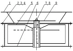
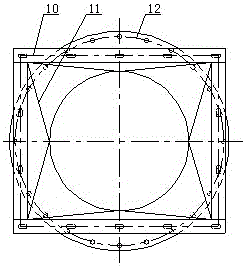
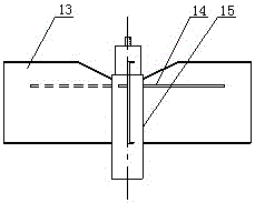
[0023] The corn harvester fan chopping device includes a feeding port 1, a bolt 2, a nut 3, a gasket 4, a fan blade welding 5, a fan casing welding 6, a shaft nut 7, and a shaft pad slice 8 and shredding blade 9; the feeding port 1 is connected with the fan housing welding 6 through bolts 2, nuts 3 and washers 4, the fan blade welding 5 is installed inside the fan housing welding 6, and the fan blade welding Combined 5 is made up of 4 rotating blades 13, 4 rotating blades 14 and a rotating shaft 15. The 4 rotating blades 13 are evenly arranged on the rotating shaft 15 along the circumference, and the 4 rotating blades 14 are installed on the 4 rotating blades 13 respectively. One end of the rotating shaft 15 passes through the lower flange 1...


PUM


Abstract

The invention relates to a shredding device for a maize harvesting machine impurity removal draught fan. The shredding device comprises a discharging opening, a bolt, a nut, a gasket, a fan blade seam, a draught fan shell seam, an axle nut, an axle gasket and a shredding blade. The discharging opening and the fan shell seam are connected through the bolt, the nut and the gasket. The fan blade seam is installed inside the fan shell seam. The fan blade seam is composed of four rotating vanes, four rotating blades and a rotating shaft, the four rotating vanes are uniformly arranged on the rotating shaft in the circumferential direction, the four rotating blades are installed on the four rotating vanes respectively, one end of the rotating shaft penetrates through a lower flange in the fan shell seam to be connected with a motor, the other end of the rotating shaft is provided with the shredding blade, and the shredding blade is fixed through the axle nut and the axle gasket. Due to the fact that maize straw and other impurities are cut through the shredding blade and the rotating blades two times, particles become finer and smaller, the field returning effect is better, the impurity removal draught fan is not likely to be blocked, the number of impurities entering a peeling machine is small, the service life of the peeling machine is prolonged, and economic benefits are created.

Description

technical field [0001] The invention relates to the technical field of corn harvester equipment manufacturing, in particular to a corn harvester chopping device for miscellaneous discharge fans. Background technique [0002] At present, the miscellaneous fan device is mainly used in corn harvester equipment. Usually, the miscellaneous fan device in the corn harvester adopts the rotating blade type without a chopping device. This structure can only discharge some impurities such as corn stalks, and the rest Impurities enter the peeling machine together with the corn fruit, which increases the load of the peeling machine and shortens the life of the peeling machine; moreover, the discharged impurity particles are large, and the effect of returning to the field is poor; and the coarse corn stalks and other impurities are easy to block the miscellaneous discharge fan, resulting in The miscellaneous fan cannot work normally, causing great obstacles to the use of farmers and reduc...

Claims


Application Information

Patent Timeline
IPC IPC(8): A01F12/44A01F12/40
Inventor 韩建伟乔彦锋王世秀胡泽明顾智原
Owner YONGMENG MACHINERY CO LTD
Learn More