
Detachable assembly-type road steel bridge carrying and erecting vehicle

A dismantling and prefabricated technology, applied in construction and other directions, can solve the problems affecting the truss docking efficiency, the overall non-removal, and the fixed position. Effect

Active Publication Date: 2017-05-24
NAT UNIV OF DEFENSE TECH
View PDF7 Cites 0 Cited by
  • Summary
  • Abstract
  • Description
  • Claims
  • Application Information

AI Technical Summary

Problems solved by technology

There are currently two types of auxiliary erection equipment for prefabricated highway steel bridges. One is propulsion equipment, such as flat rolls, rockers, lower string joints, and inclined chords, and the other is installation tools, such as wrenches, crowbars, and mallets. etc., but none of these devices can realize the handling and erection of trusses and beams
[0004] Although the existing transport and erection equipment (vehicles) can carry and erect trusses and beams, most of the existing transport and erection equipment (vehicles) are integrally non-detachable, and their positions are fixed and invariable. The lifting of the hydraulic oil pipe of the auxiliary operation equipment is adjusted, and the equipment itself cannot be adjusted, so it is difficult to carry items of different specifications; considering the complex and changeable operation area, sometimes the height of the truss may be close to the height of the upper surface of the forklift, and it will not be possible to operate at this time, and it will not be possible to achieve super Low-level operation; at the same time, due to the excessive friction between the surface of the shelf and the truss, the movement is laborious, which affects the efficiency of the truss docking

Method used


Image

  • Detachable assembly-type road steel bridge carrying and erecting vehicle
  • Detachable assembly-type road steel bridge carrying and erecting vehicle
  • Detachable assembly-type road steel bridge carrying and erecting vehicle

Examples


Embodiment Construction

[0044] The present invention will be further described in detail below in conjunction with the accompanying drawings and specific embodiments.

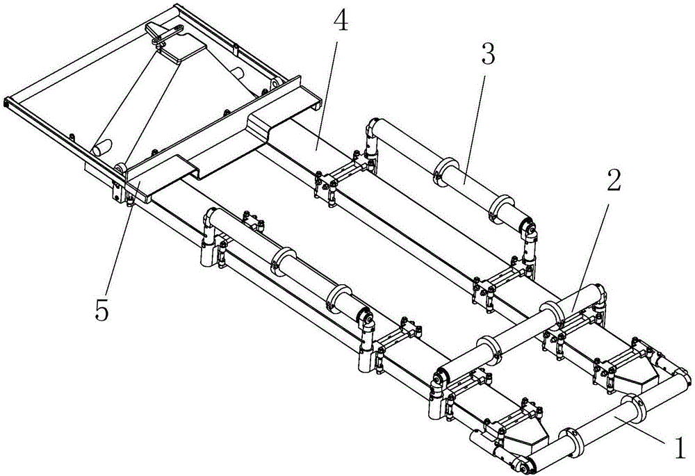
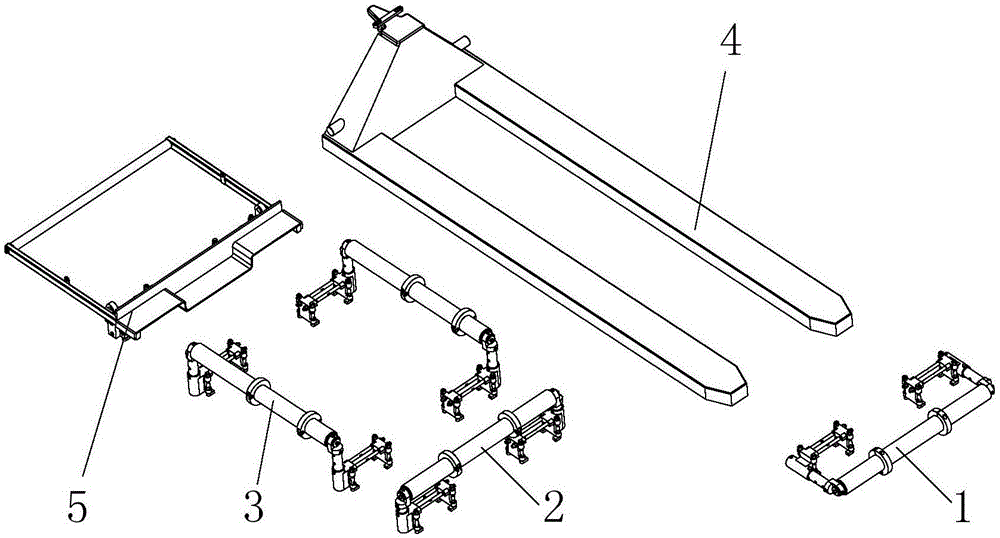
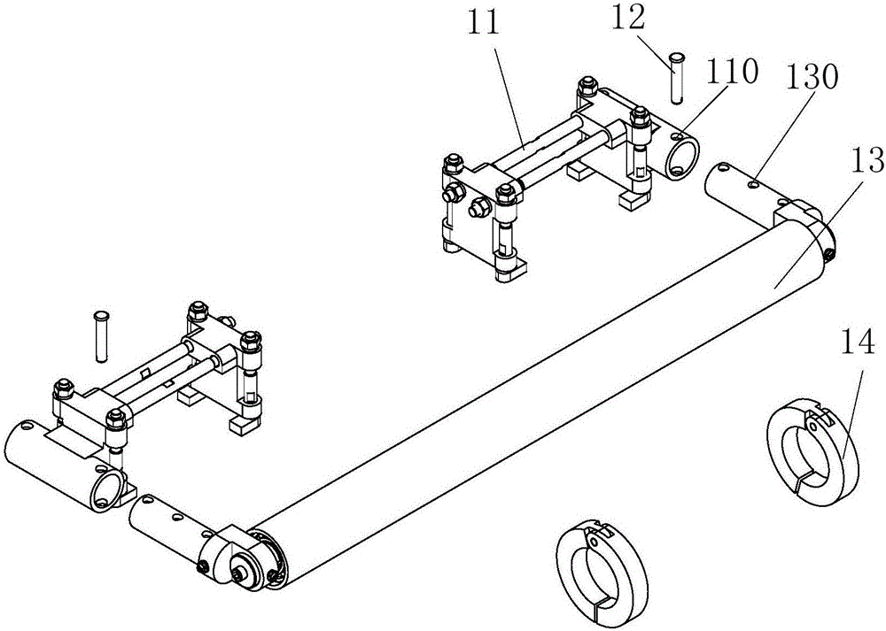
[0045] As shown in Figure 1(a) and Figure 1(b), the detachable assembled road steel bridge handling and erecting vehicle consists of a front lifting roller assembly 1, a middle lifting roller assembly 2, a side lifting roller assembly 3, and a vehicle body. 4 and the lifting plate assembly 5; the front lifting roller assembly 1 straddles the two forks of the car body 4 and is installed on the front side of the car body 4 in the horizontal direction; the middle lifting roller assembly 2 straddles the two forks of the car body 4 The fork is mounted on the middle side of the car body 4 in the vertical direction; the two side lift roller assemblies 3 are respectively installed on the two forks of the car body 4 along the longitudinal direction, and are respectively installed on both sides of the car body 4; the lifting plate assembly 5 is...


PUM


Abstract

The invention provides a detachable assembly-type road steel bridge carrying and erecting vehicle. The detachable assembly-type road steel bridge carrying and erecting vehicle comprises a front raising roller assembly, a middle raising roller assembly, side raising roller assemblies, a vehicle body and a raising plate assembly; the front raising roller assembly stretches across two forks of the vehicle body, and is installed at the front side of the vehicle body along a horizontal direction; the middle raising roller assembly stretches across the two forks of the vehicle body, and is installed at the middle side of the vehicle body along a vertical direction; the two side raising roller assemblies are respectively installed on the two forks of the vehicle body along a longitudinal direction, and are respectively installed at two sides of the vehicle body; and the raising plate assembly is installed at the rear side of the vehicle body. Compared with the prior art, a majority of assemblies are of a detachable structure and installed on the vehicle body, and no structure of an original forklift truck needs to be changed; by adopting a modularized design method, a majority of components in most assemblies are universal, so that more easiness in maintenance and guarantee can be realized; and the structure of the carrying and erecting vehicle is adjustable, so that the application range is greatly enlarged, and an ultra-low pose operation can be completed.

Description

technical field [0001] The invention belongs to the technical field of engineering operation equipment, and in particular relates to a detachable assembled highway steel bridge transport and erection vehicle. Background technique [0002] Prefabricated highway steel bridges, as one of the war preparation materials reserved by the Ministry of Communications on behalf of the country, have been widely used for decades, whether in wartime highway bridge repairs and rush construction, overcoming river obstacles, or in peacetime earthquake and flood rescue and disaster relief , traffic security are playing an irreplaceable role. [0003] During the erection process of the prefabricated highway steel bridge, it is necessary to rely on manpower to move the trusses, beams, etc. to the transport and erection vehicle, and then carry out docking. There are currently two types of auxiliary erection equipment for prefabricated highway steel bridges. One is propulsion equipment, such as f...

Claims


Application Information

Patent Timeline
IPC IPC(8): E01D15/127
CPCE01D15/127
Inventor 宋殿义黄益民徐伟刘飞
Owner NAT UNIV OF DEFENSE TECH
Learn More