Memory switching method and device

A switching device and memory technology, applied in memory systems, instruments, memory address/allocation/relocation, etc., can solve the problems of short access time and long access time, and achieve the effect of improving data access speed and ensuring data consistency

Inactive Publication Date: 2017-05-24
SANECHIPS TECH CO LTD
View PDF10 Cites 4 Cited by
  • Summary
  • Abstract
  • Description
  • Claims
  • Application Information

AI Technical Summary

Problems solved by technology

However, the disadvantage of this is that after the cache has passed the query delay, if it hits, the access time is relatively short, and if it does not hit, the access time is still very long

Method used


Image

  • Memory switching method and device
  • Memory switching method and device
  • Memory switching method and device

Examples


Embodiment Construction

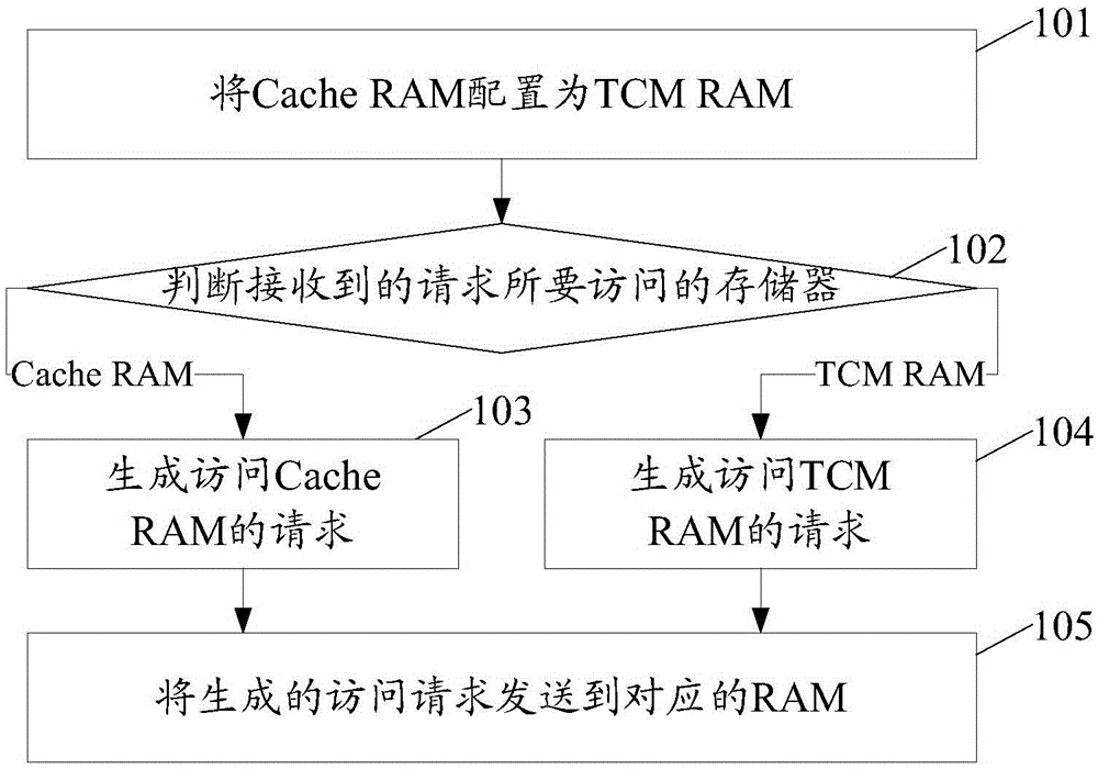
[0031] In the embodiment of the present invention, first Cache RAM is configured as TCM RAM; Then judge the memory that the request that receives needs to visit, when the memory that the request that receives needs to visit is Cache RAM, generate the request of accessing Cache RAM; When receiving The type of memory to be accessed by the request is TCMRAM, a request for accessing the TCM RAM is generated, and then the generated access request is sent to the corresponding RAM.

[0032] The implementation of the technical solutions of the present invention will be further described in detail below in conjunction with the accompanying drawings and specific embodiments. figure 1 It is a schematic flow chart of a memory switching method according to an embodiment of the present invention, as shown in figure 1 As shown, the memory switching method of this embodiment includes the following steps:

[0033] Step 101: Cache RAM is configured as TCM RAM;

[0034] The described configura...


PUM


Abstract

The invention provides a memory switching method and device. The method comprises the following steps that: configuring a Cache RAM (Random Access Memory) into a TCM (Tightly Coupled Memory) RAM; judging a memory to be accessed by a received request, and when the memory to be accessed by the received request is the Cache RAM, generating a request for accessing the Cache RAM; when the memory to be accessed by the received request is the TCM RAM, generating a request for accessing the TCM RAM; and sending the generated access request to the corresponding RAM. The invention also provides a memory switching device.

Description

technical field [0001] The invention relates to data storage technology, in particular to a memory switching method and device for realizing dynamic switching between a cache memory (Cache) and a tightly coupled memory (TCM, Tightly Coupled Memory). Background technique [0002] In the processor architecture, the storage system is hierarchical. The closer the memory is to the core, the smaller the scale and the faster the read and write speed. In the existing processor system, in addition to L1 Cache and L2 Cache, most processor systems also have L1 TCM; L1 TCM is fast and the access time is deterministic, but it is usually small in scale and cannot fully meet the actual requirements. need. When a program that requires high access speed works or the data cannot fit in the L1 TCM, the usual practice is to define the program or the corresponding data as a cacheable attribute and store it in the Cache. However, the disadvantage of this is that after the cache has passed the q...

Claims


Application Information

Patent Timeline
Patent Type & Authority Applications(China)
IPC IPC(8): G06F12/06
CPCG06F12/06G06F12/0638
Inventor 赵世凡孙志文
Owner SANECHIPS TECH CO LTD
Why Eureka
Try Eureka