
Portable fire hose laying vehicle

A fire hose and laying vehicle technology, which is applied in fire rescue and other directions, can solve the problems of difficult hose retraction, difficult laying of hoses, and high quality of single-drum hoses, achieving rapid laying and recycling, saving laying time, Reduce the effect of laying personnel

Active Publication Date: 2017-05-31
王敬忠
View PDF9 Cites 2 Cited by
  • Summary
  • Abstract
  • Description
  • Claims
  • Application Information

AI Technical Summary

Problems solved by technology

[0002] At present, fire brigades are generally equipped with 50m long ø65mm or ø80mm hoses for long-distance and high-rise water supply. , Put the hoses away and place them on the fire truck. With the bumping of the fire truck, the hoses are easy to scatter, and the weight of a single hose is large (not less than 50 catties), which is not conducive to the carrying and laying of the hoses on the fire site. , causing unnecessary waste of time and missing the best time for fire fighting; folded and coiled hose retraction method, after a 50m hose is rolled up, it takes up a lot of space in the equipment box, the equipment is placed in a mess, and it can be carried over a long distance It takes 2 people to assist each time, which is time-consuming and laborious. It is difficult to lay the hose and it is easy to get knotted when laying it. The efficiency of the firefighters is low and the battle is slow.

Method used


Image

  • Portable fire hose laying vehicle
  • Portable fire hose laying vehicle
  • Portable fire hose laying vehicle

Examples


Embodiment Construction

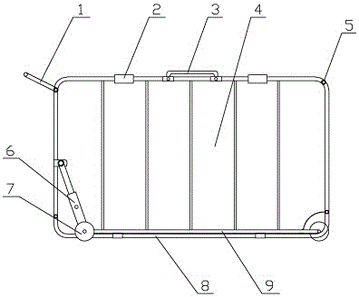
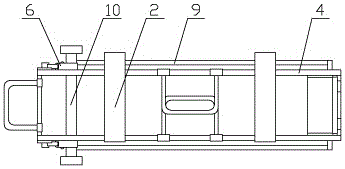
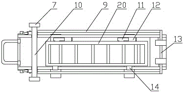
[0023] see Figure 1-Figure 6 , the present invention is a portable fire hose laying vehicle, which has a cuboid car body 4, the top and bottom surfaces of the car body are all arranged in an open structure, and the two sides of the open structure on the bottom surface of the car body are respectively provided with a wheel axle A10 and a wheel axle B13, wherein the wheel shaft B is hinged with one end of the car body, and the other end of the car body rests on the wheel shaft A, and the wheel shaft A and the wheel shaft B are connected together through two connecting rods 9, and the ends of the wheel shaft A and the wheel shaft B are provided with There are rollers 7; both ends of the wheel shaft A are also symmetrically provided with a set of car body jacking devices 6, and the two sets of car body jacking devices are respectively arranged at the front and rear sides of the car body, and the lower ends of the car body jacking devices are hinged. On the axle A, the upper end o...


PUM


Abstract

The invention relates to a portable fire hose laying vehicle. The portable fire hose laying vehicle comprises a vehicle body, wherein the top surface and the bottom surface of the vehicle body are of unenclosed structures; a wheel shaft A and a wheel shaft B are respectively arranged at the two sides of the unenclosed structure of the bottom surface of the vehicle body and are connected together through two connecting rods; idler wheels are arranged at the end parts of the wheel shaft A and the wheel shaft B; two sets of vehicle body jacking devices are respectively and symmetrically arranged at the two ends of the wheel shaft A; a hinge type water hose bottom supporting door is arranged on the unenclosed structure of the bottom of the vehicle body; a ferrule is arranged at one side of the water hose bottom supporting door; a latch is arranged at the other side of the water hose bottom supporting door; a movable handle which rotates towards front and back is arranged on the unenclosed structure of the top surface of the vehicle body; two sticking tapes are respectively arranged at the left side and right side of the movable handle; and an oblique-pulling handle and a water hose idler wheel are respectively arranged at the left side and right side of the top surface of the vehicle body. According to the portable fire hose laying vehicle, the transportation is convenient, the occupying space is small, water hoses can be expanded quickly and conveniently without knot tying, the efficiency is high, the labor can be saved, and due to existence of the water hose idler wheels, the friction is small when the water hose is expanded, and therefore, the damage of the water hose is small.

Description

technical field [0001] The invention relates to the technical field of auxiliary equipment for fire protection, in particular to a portable fire hose laying vehicle. Background technique [0002] At present, fire brigades are generally equipped with 50m long ø65mm or ø80mm hoses for long-distance and high-rise water supply. , Put the hoses away and place them on the fire truck. With the bumping of the fire truck, the hoses are easy to scatter, and the weight of a single hose is large (not less than 50 catties), which is not conducive to the carrying and laying of the hoses on the fire site. , causing unnecessary waste of time and missing the best time for fire fighting; folded and coiled hose retraction method, after a 50m hose is rolled up, it takes up a lot of space in the equipment box, the equipment is placed in a mess, and it can be carried over a long distance It takes 2 people to assist each time, which is time-consuming and labor-intensive. It is difficult to lay the h...

Claims


Application Information

Patent Timeline
IPC IPC(8): A62C33/00
CPCA62C33/00
Inventor 王敬忠王志明陈沿池柯俊
Owner 王敬忠
Learn More