
A watch case automatic disassembly device

A technology for automatic disassembly and assembly of watch cases, applied in metal processing equipment, metal processing, manufacturing tools, etc., can solve the problems of excessive force, easy to scratch the case, uncontrollable rotating force, etc., to improve waterproofness, reduce Worker fatigue and the effect of improving work efficiency

Active Publication Date: 2019-06-18
GEER TECH CO LTD
View PDF9 Cites 0 Cited by
  • Summary
  • Abstract
  • Description
  • Claims
  • Application Information

AI Technical Summary

Problems solved by technology

[0003] Since the screw connection of the back case of the watch is very tight, the labor intensity is relatively high when disassembling the case, and the rotational force used during assembly cannot be controlled, and the force may be too large or too small, resulting in poor water resistance and air tightness. , and it is very easy to scratch the case during the alignment process between the positioning claw and the groove (slot), resulting in poor appearance of the product

Method used


Image

  • A watch case automatic disassembly device
  • A watch case automatic disassembly device
  • A watch case automatic disassembly device

Examples


Embodiment 1

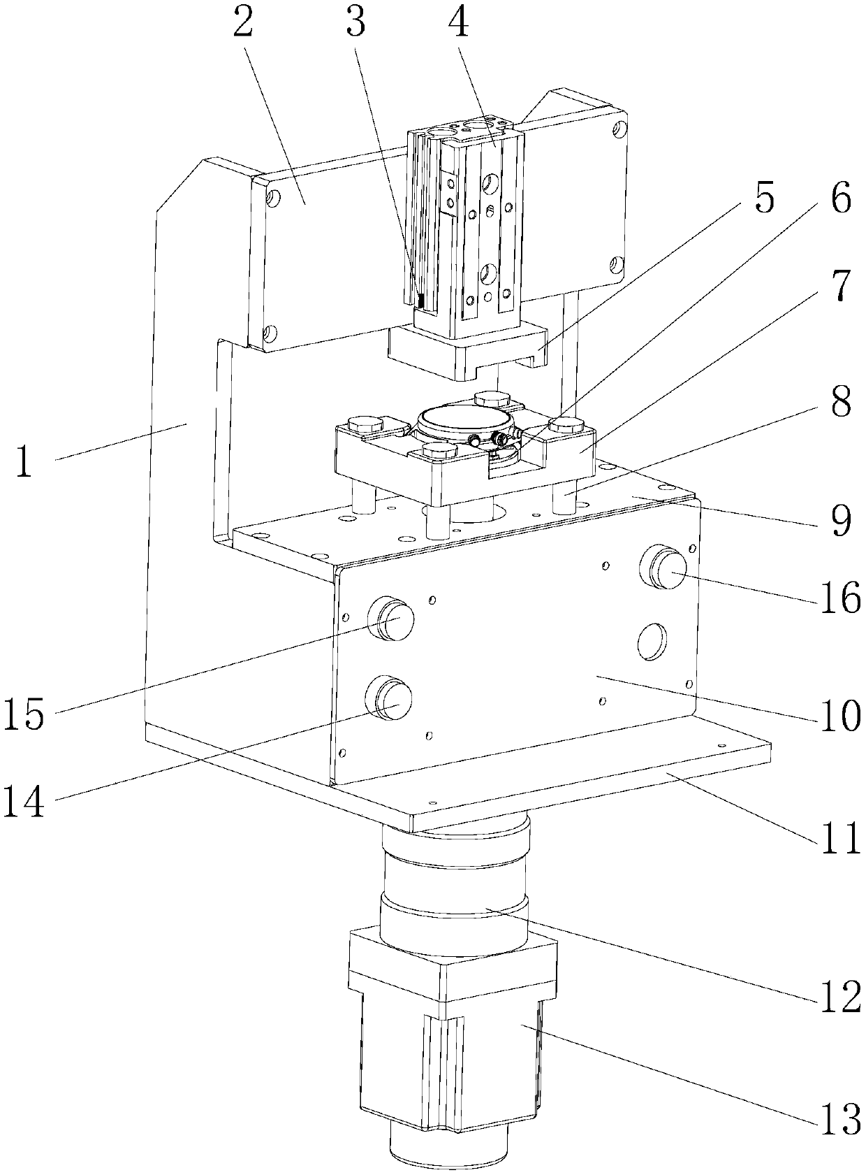
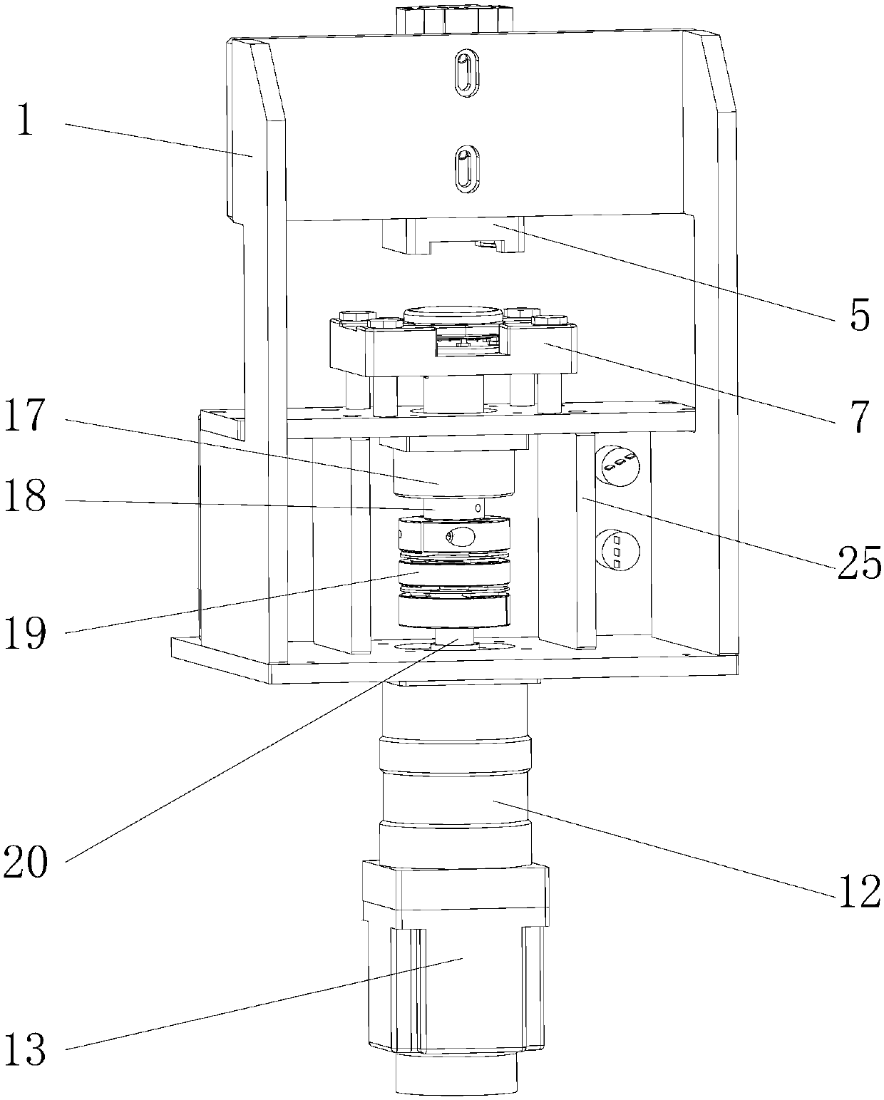
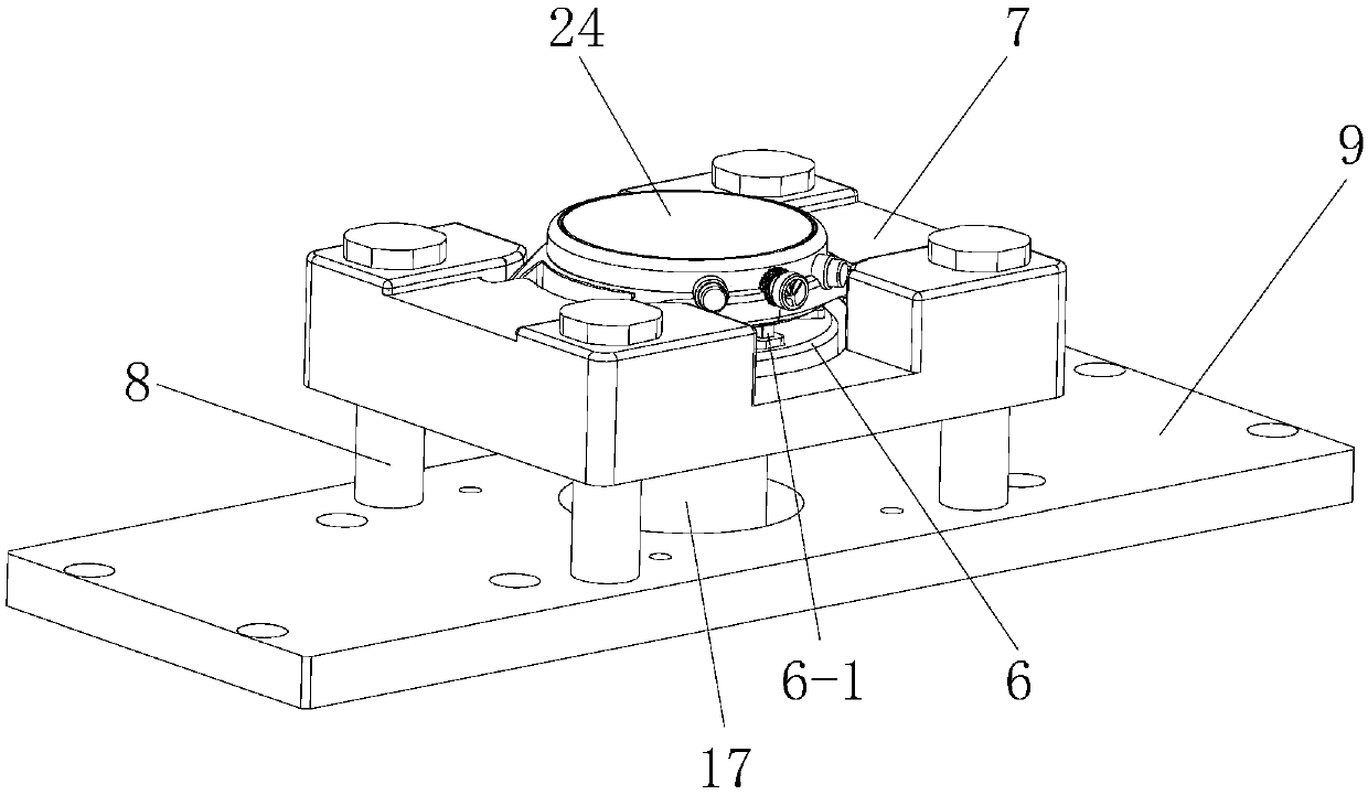
[0034] Such as figure 1 , figure 2 , image 3 , Figure 5 Shown is one of the embodiments of the present invention. In this embodiment, a watch case automatic disassembly and assembly device is provided with a frame 1, and a watch case fixing block 7 is installed and fixed in the frame 1, which is ready to be disassembled. The watch head 24 is positioned in the watch case fixing block 7, and the watch head 24 rear case is placed downward; the watch case fixing block 7 is provided with a vertical through hole, and the watch case disassembly block 6 is installed in the through hole, and the watch case The dismounting block 6 can rotate relative to the watch case fixing block 7 , and the watch case dismounting block 6 is preferably designed in a disc shape and rotates around its own axis.

[0035] The watch case dismounting block 6 is provided with some upward positioning claws 6-1, and the positioning claws 6-1 stretch into the draw-in groove of the meter head 24 rear shell,...

Embodiment 2

[0054] In this embodiment, the difference from Embodiment 1 is that a bearing is provided in the vertical through hole of the watch case fixing block 7 to support the rotation of the watch case dismounting block 6, and the bearing can be installed in a radial support manner. Such a design can improve the stability of the rotation of the case disassembly block 6 and improve the disassembly quality.

[0055] Other structures of the watch case automatic dismounting device in this embodiment are the same as those in Embodiment 1, and will not be described again here.

Embodiment 3

[0057] In this embodiment, the difference from Embodiment 1 is that the spacing between the positioning claws 6-1 can be automatically adjusted to adapt to different types of meter back cases. Such a design can expand the applicability of the watch case dismounting block 6, and facilitate dismounting and assembling of various watch cases.

[0058] In order to achieve this technical purpose, a guide groove can be designed for each positioning claw 6-1 in the watch case dismounting block 6, the direction of the guide groove is arranged along the radial direction of the dismounting block 6, and a spring in the horizontal direction is arranged in the guide groove The positioning claw 6-1 is supported, so as to realize the self-adaptive function of the positioning claw 6-1.

[0059] Other structures of the watch case automatic dismounting device in this embodiment are the same as those in Embodiment 1, and will not be described again here.


PUM


Abstract

The invention discloses automatic watch case disassembling and assembling equipment which solves the technical problems that in the prior art, a rear watch case needs to be manually disassembled and assembled, the labor intensity is high, operation efficiency is low, and the assembling effect is not ideal. The automatic watch case disassembling and assembling equipment comprises a frame, a watch case fixing block is fixedly mounted in the frame, a watch head to be disassembled and assembled is positioned in the watch case fixing block, and a rear watch head case is placed downwards; a vertical through hole is formed in the watch case fixing block, a watch case disassembling and assembling block is mounted in the through hole and can rotate relative to the watch case fixing block, and a plurality of upward positioning claws are arranged on the watch case disassembling and assembling block and stretch into clamping grooves in the rear watch head case. A servo motor is mounted in the frame, and a transmission shaft of the servo motor is connected with the watch case disassembling and assembling block and drives the watch case disassembling and assembling block to rotate, so that the rear watch head case is disassembled and assembled.

Description

technical field [0001] The invention relates to a device capable of automatically disassembling and assembling a product shell, in particular to a device for automatically disassembling and assembling a watch case. Background technique [0002] At present, in the assembly process of quartz watches and mechanical watches, most of the watch cases are tested for water resistance and air tightness first, and then the internal movement is assembled. For this reason, the watch cases need to be disassembled and assembled repeatedly. Most of the existing disassembly and assembly methods are realized by manual disassembly and assembly tools. The manual disassembly and assembly jig has three positioning claws. Align the three positioning claws with the groove (slot) on the back of the back case of the watch, and rotate it firmly. The case is disassembled. [0003] Since the screw connection of the back case of the watch is very tight, the labor intensity is relatively high when disas...

Claims


Application Information

Patent Timeline
Patent Type & Authority Patents(China)
IPC IPC(8): B23P19/04
CPCB23P19/04
Inventor 尹元涛王存
Owner GEER TECH CO LTD
Learn More