A suspension rail vehicle pickup system

A rail car and electric system technology, applied to the elevated railway system with suspended vehicles, current collectors, motor vehicles, etc., can solve the problems of high cost, excessive volume, and large volume, and achieve the effect of high reliability

Active Publication Date: 2020-05-19
SHENZHEN XIAODE TECH CO LTD
View PDF4 Cites 0 Cited by
  • Summary
  • Abstract
  • Description
  • Claims
  • Application Information

AI Technical Summary

Problems solved by technology

But bulky and costly
[0003] The other is the safety trolley line. The collector runs in the rubber sleeve of the trolley line. The problem is that the speed is limited, and it is well adapted to the local track section to take power through the trolley line. The local section is powered by a battery, which requires frequent entry and exit. The case of the trolley line
However, the size of the existing safety trolley line collector is too large, and it is difficult to apply it inside the narrow pipe rail of the micro-rail intelligent transportation.

Method used


Image

  • A suspension rail vehicle pickup system
  • A suspension rail vehicle pickup system
  • A suspension rail vehicle pickup system

Examples


Embodiment Construction

[0026] In order to understand the implementation process and implementation effect of the present invention more clearly, the following will be described in detail in conjunction with the accompanying drawings. It should be understood that the embodiments do not limit the protection scope of the present invention.

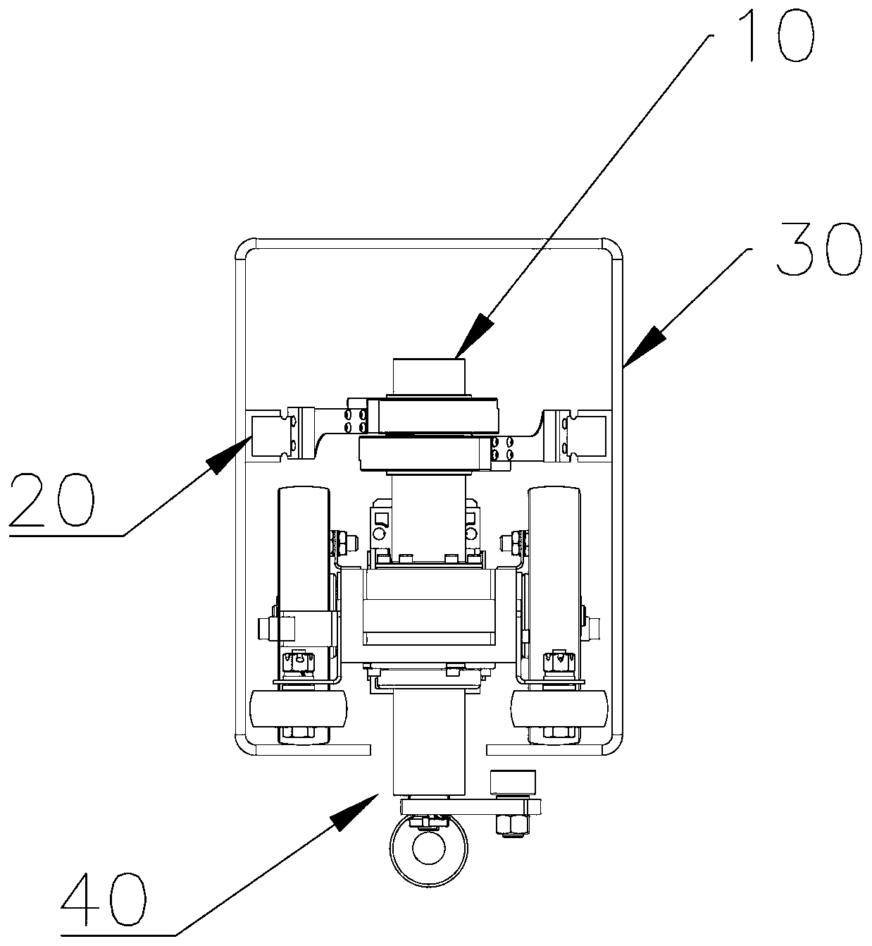
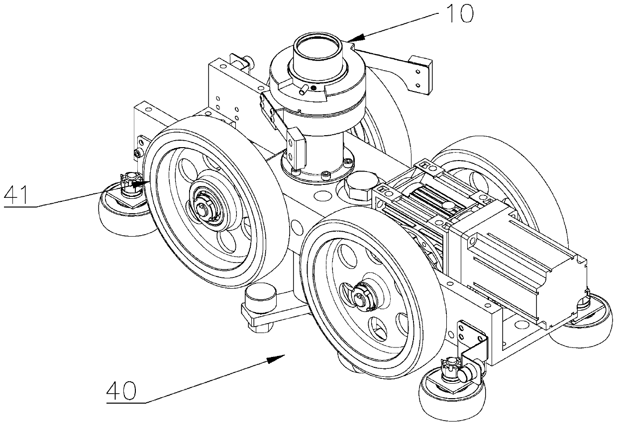
[0027] A suspension rail car power-taking system, such as figure 1 Shown: include power-taking device 10, power supply device 20, railcar traveling mechanism 40 and track 30, railcar is suspended below railcar traveling mechanism 40. Such as figure 2 As shown, the rail car traveling mechanism 40 is provided with two sets of front and rear travel wheels 41, all or part of the travel wheels walk along the track 30 under the action of the motor, and the motor takes power from the power supply connected to the power supply device 20 through the power taking device 10.

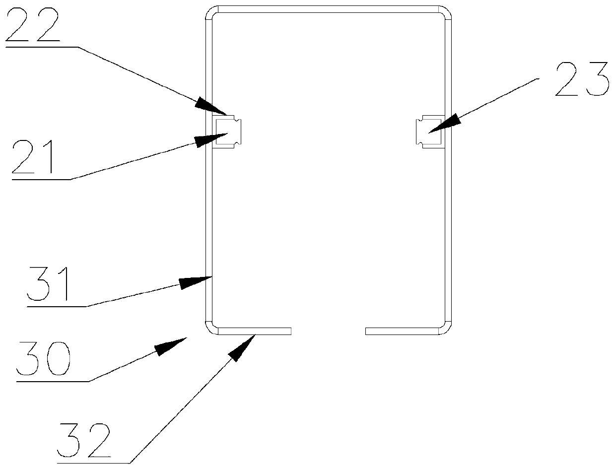
[0028] Such as image 3 As shown, the power supply device 20 includes a positive trolley line 21 ...


PUM


Abstract

The invention discloses a suspension railcar electricity-taking system which comprises a power supply device, a power taking device, a railcar travelling mechanism and a rail. The power supply device comprises an anode slide wire and a cathode slide wire. The anode slide wire and the cathode slide wire are arranged on the side of a left side rail and the side of a right side rail respectively. The railcar travelling mechanism is arranged on the rail, a railcar is suspended below the railcar travelling mechanism, the top of the railcar travelling mechanism is provided with the power taking device, the power taking device comprises an anode electric brush and a cathode electric brush, the power taking device takes power by utilizing the anode electric brush to contact the anode slide wire on the rail and utilizing the cathode electric brush to contact the cathode slide wire on the rail to provide power for the railcar travelling mechanism. The power-taking system is small in size and stable in structure, adapts to high-speed running and also facilitates frequent switching between power supply through the slide wires and power supply through a battery.

Description

technical field [0001] The invention relates to the technical field of miniature rail transit, in particular to a power-taking system for a suspended rail car. Background technique [0002] There are two types of sliding contacts used in large-scale rail vehicles, one of which is a rigid body sliding contact line, which can withstand large currents and high speeds. But the volume is large and the cost is high. [0003] The other is the safety trolley line. The collector runs in the rubber sleeve of the trolley line. The problem is that the speed is limited, and it is well adapted to the local track section to take power through the trolley line. The local section is powered by a battery, which requires frequent entry and exit. The case of sliding contact lines. However, the volume of the existing safety trolley line collector is also too large, and it is difficult to be applied to the inside of the narrow pipe rail of the micro-rail intelligent transportation. Contents o...

Claims


Application Information

Patent Timeline
Patent Type & Authority Patents(China)
IPC IPC(8): B60L5/38B61B3/00
CPCB60L5/38B60L2200/26B61B3/00
Inventor 葛大力
Owner SHENZHEN XIAODE TECH CO LTD
Why Eureka
Try Eureka