Flying shear blade replacing method

A replacement method and technology of flying shears, applied in the field of flying shears blade replacement, can solve the problem of long time to replace flying shears blades, and achieve the effect of reducing manpower utilization, improving speed, reliability and safety.

Inactive Publication Date: 2015-09-02
SHOUGANG JINGTANG IRON & STEEL CO LTD
View PDF9 Cites 3 Cited by
  • Summary
  • Abstract
  • Description
  • Claims
  • Application Information

AI Technical Summary

Problems solved by technology

[0007] The invention provides a method for replacing the blades of flying shears to solve the technical problem in the prior art that it takes too long to replace the blades of flying shears

Method used


Image

  • Flying shear blade replacing method
  • Flying shear blade replacing method
  • Flying shear blade replacing method

Examples


Embodiment Construction

[0043] The invention provides a method for replacing the blades of flying shears to solve the technical problem in the prior art that it takes too long to replace the blades of flying shears.

[0044] The technical solution in the embodiment of the present application is to solve the above-mentioned technical problems, and the general idea is as follows:

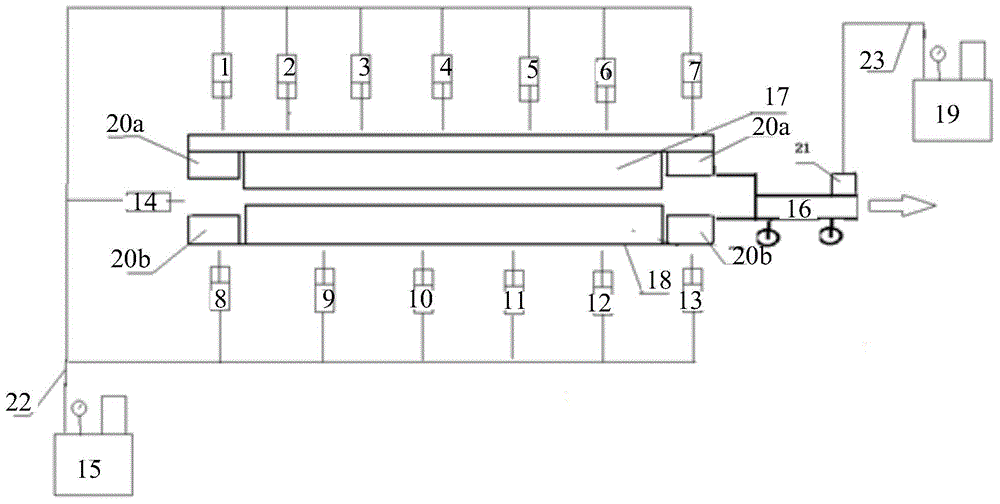
[0045] When replacing the cutting blades of the flying shears, pressurize the upper blade holder locking cylinder, the lower blade holder blade locking cylinder and the shearing blade ejection hydraulic cylinder of the flying shears through the first oil pump, and the first oil pump is Compared with the existing manual manual pump, the movable oil pump has a higher reliability of the pressure gauge, reduces the manpower utilization rate, and saves the time-consuming separate pressing of the upper and lower tool rest locking cylinders of the flying shears;

[0046] Furthermore, the first upper cutting edge and the first lower...


PUM


Abstract

The invention relates to the technical field of steel rolling, discloses a flying shear blade replacing method, aims at solving the technical problem that flying shear blade replacing time is long in the prior art. The flying shear blade replacing method includes: controlling flying shears in power outage and voltage outage status; returning shear blades of the flying shears to a shear blade zero position; adjusting the distance between a first upper shear blade and a first lower shear blade of the flying shears through a pneumatic motor; respectively adding oil pipes on a top knife carrier shear blade locking cylinder and a bottom knife carrier shear blade locking cylinder; pressing the top knife carrier shear blade locking cylinder, the bottom knife carrier shear blade locking cylinder and a shear blade ejection hydraulic cylinder of the flying shears through a first oil pump; dismantling safety pins; using a shear blade pulling device in a shear blade replacing device to connect the first upper shear blade and the first lower shear blade; pulling the upper shear blade and the lower shear blade out of a flying shear body; installing a second upper shear blade and a second lower shear blade in the flying shear body; respectively installing the safety pins on the second upper shear blade and the second lower shear blade; dismantling the oil pipes. The flying shear blade replacing method achieves the technical effect of reducing the flying shear blade replacing time.

Description

technical field [0001] The invention relates to the technical field of steel rolling, in particular to a method for replacing cutting blades of flying shears. Background technique [0002] In the current metallurgical enterprises, when the blades of the crank-type flying shears are replaced, the blade locking cylinder is usually pressurized manually, and the pressure value is monitored by a special person. When the pressure data reaches the preset value, the blade puller is used to pull the out the scissors. [0003] The solutions in the prior art have at least the following technical problems: [0004] 1. The locking cylinders of the upper and lower tool holders of flying shears are separately pressed. The traditional process generally uses a manual hand pump, which wastes a lot of manpower and time. The response of the hand pump to adjust the pressure is relatively slow, and the pressure gauge of the hand pump is less reliable. [0005] 2. The extraction device of the cu...

Claims


Application Information

Patent Timeline
IPC IPC(8): B23D33/00B23D25/02
Inventor 张建峰韩娜张维中
Owner SHOUGANG JINGTANG IRON & STEEL CO LTD
Why Eureka
Try Eureka