Positioning stand column for inclined cantilever

A technology for positioning columns and wrist arms, applied in the direction of overhead lines, etc., can solve the problems of cumbersome connectors and uncompact structure, and achieve the effects of simple connection, improved product production efficiency, and functional optimization.

Active Publication Date: 2017-05-31
CHINA RAILWAYS CORPORATION +3
View PDF10 Cites 2 Cited by
  • Summary
  • Abstract
  • Description
  • Claims
  • Application Information

AI Technical Summary

Problems solved by technology

One is in the case of small side boundaries, if the traditional connection method is used, the connection space cannot accommodate the above three parts, the connection parts are slightly cumbersome, and the structure is not compact

Method used


Image

  • Positioning stand column for inclined cantilever
  • Positioning stand column for inclined cantilever
  • Positioning stand column for inclined cantilever

Examples


Embodiment Construction

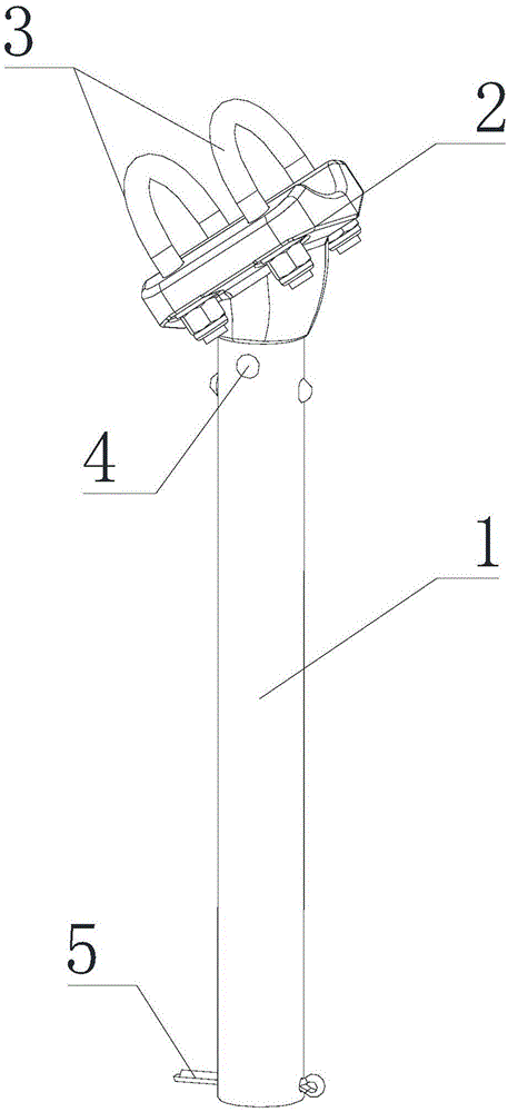
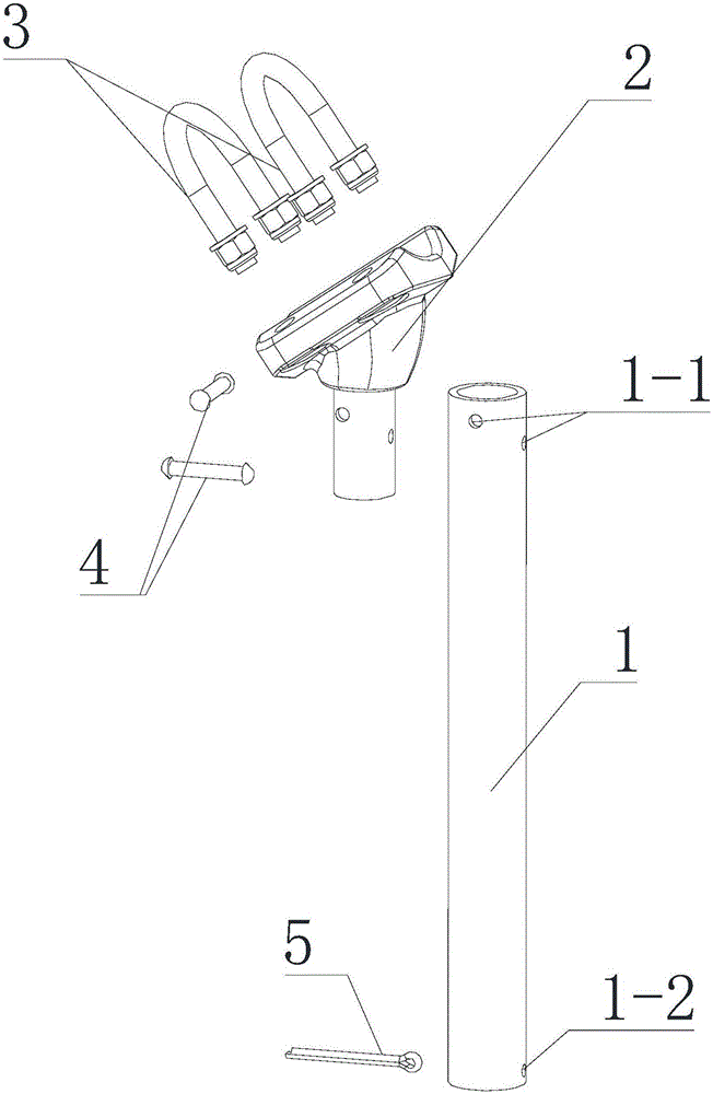
[0018] Such as figure 1 with figure 2 The positioning column for the inclined wrist arm shown includes a positioning tube 1 and a support 2, the support 2 is fixed on one end of the positioning tube 1, and a U-shaped bolt 3 is arranged on the support 2, and the U-shaped bolt 3 cooperates with the support 2 to Secure the oblique arm.

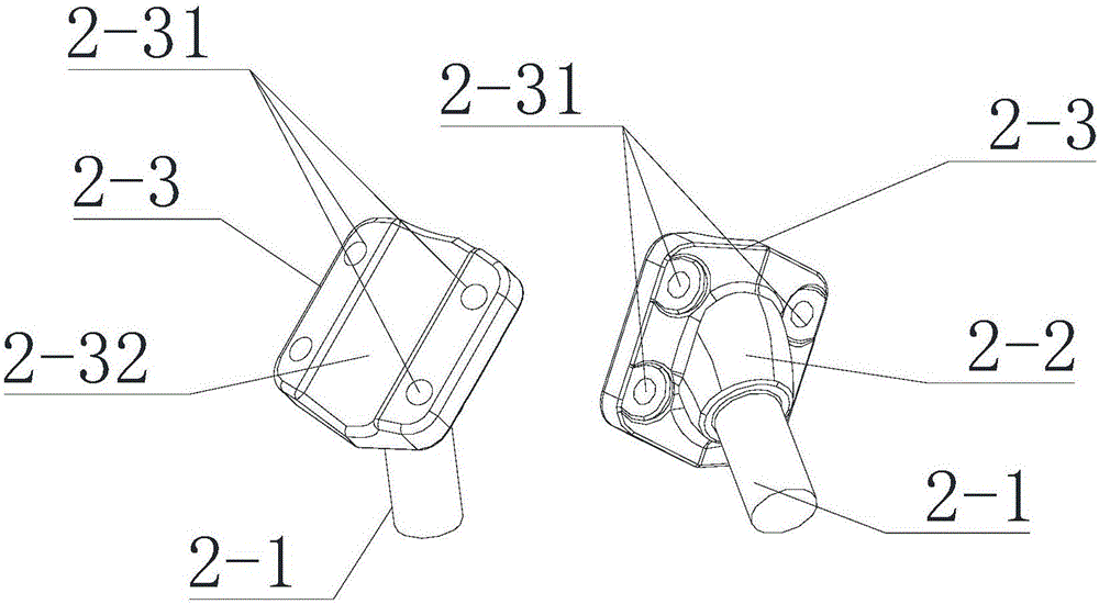
[0019] Such as image 3 The shown support 2 includes an insertion part 2-1, a transition table 2-2 and a fixed plate 2-3, the insertion part 2-1, the transition table 2-2 and the fixed plate 2-3 are integrally forged, and the insertion part 2-1 is inserted into the positioning tube 1 in a columnar shape and connected with the positioning tube 1. There are two installation holes 2-11 on the socket part 2-1. 1 is provided with a through hole 1-1, and the through hole 1-1 and the installation hole 2-11 are matched with each other. A rivet 4 is arranged in the through hole 1-1 and the installation hole 2-11 to connect the positioning tube 1 with ...


PUM


Abstract

The invention discloses a positioning stand column for an inclined cantilever. The positioning stand column comprises a positioning pipe (1) and a support (2). The support (2) comprises an insertion portion (2-1) inserted into one end of the positioning pipe (1), a transition table (2-2) is arranged on the insertion portion (2-1), a fixing plate (2-3) for supporting the inclined cantilever is arranged on the transition table (2-2), a connecting hole (2-31) is formed in the fixing plate (2-3), a U-shaped bolt (3) connected to the interior of the connecting hole (2-31) to fix the inclined cantilever is arranged on the fixing plate (2-3). A groove (2-32) for containing the inclined cantilever is formed in the fixing plate (2-3). A fixedly-connected rivet (4) is arranged on the support (2) and the positioning pipe (1). By adopting the structure, the numbers of positioning rings, positioning pipes and fasteners are decreased, on-site construction and installation and follow-up maintenance are convenient, the product safety is improved, and potential operational risk is reduced.

Description

technical field [0001] The invention relates to the technical field of catenary equipment for electrified railways, in particular to a positioning column for an inclined arm. Background technique [0002] In the electrified railway catenary system, the positioning support plays the role of connecting the positioning pipe and the positioner, and is an important connecting part in the positioning device. In the catenary system that has been built and operated in my country, the traditional way is used to connect under the standard side limit (the distance between the side of the column and the center of the line). The three parts are connected to each other. One is that in the case of a small side boundary, if the traditional connection method is used, the connection space cannot accommodate the above three parts, and the connection parts are slightly cumbersome and the structure is not compact. In response to these problems, it is proposed to integrate and optimize the funct...

Claims


Application Information

Patent Timeline
Patent Type & Authority Applications(China)
IPC IPC(8): B60M1/20
CPCB60M1/20
Inventor 罗健韩凌青崔校玉韩宝峰闫军芳李海峰唐爱军
Owner CHINA RAILWAYS CORPORATION
Why Eureka
Try Eureka