
Washing machine

A washing machine and water flow channel technology, applied in the field of washing machines, can solve the problems of increased washing ratio of clothes, low water outlet strength, and inconspicuous winding effect of clothes, so as to increase strength and water spray volume, reduce water flow potential energy loss, and reduce washing The effect of water consumption

Pending Publication Date: 2017-05-31
WUXI LITTLE SWAN ELECTRIC CO LTD
View PDF7 Cites 8 Cited by
  • Summary
  • Abstract
  • Description
  • Claims
  • Application Information

AI Technical Summary

Problems solved by technology

[0002] When washing clothes, the pulsator washing machine relies on the positive and negative rotation of the pulsator to form an alternating reciprocating water flow to wash the clothes. When washing the clothes, it is easy to cause the clothes to be entangled, which not only affects the cleaning efficiency of the washing machine but also damages the clothes. In order to prevent the clothes from being entangled, During the work of the pulsator washing machine, by setting the spray waterfall plate in the inner cylinder of the washing machine, the water flow is used to spray the waterfall from the top of the clothes to rinse the clothes. The pulsator washing machine in the related art has only one position to fix the spray waterfall mouth. When it is less, the water output of the waterfall outlet is small and the water output intensity is low, and the washing ratio of the clothes is improved and the winding effect of the clothes is not obvious. The device pumps the water at the bottom of the pulsator to the water outlet of the waterfall plate. At this time, the water flow is strong and the water output is large, but the production cost of the pulsator washing machine is increased.

Method used


Image

  • Washing machine
  • Washing machine
  • Washing machine

Examples


Embodiment Construction

[0035] Embodiments of the present invention are described in detail below, examples of which are shown in the drawings, wherein the same or similar reference numerals designate the same or similar elements or elements having the same or similar functions throughout. The embodiments described below by referring to the figures are exemplary and are intended to explain the present invention and should not be construed as limiting the present invention.

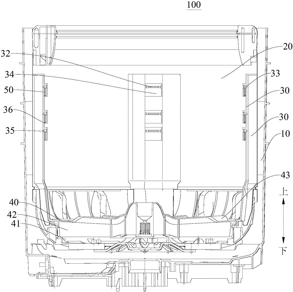
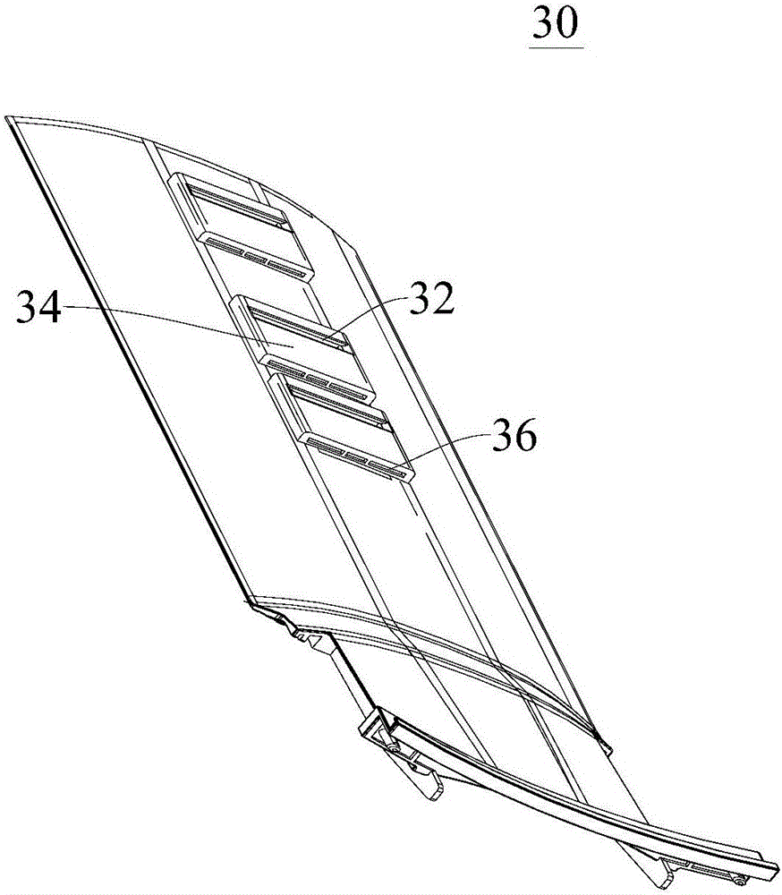
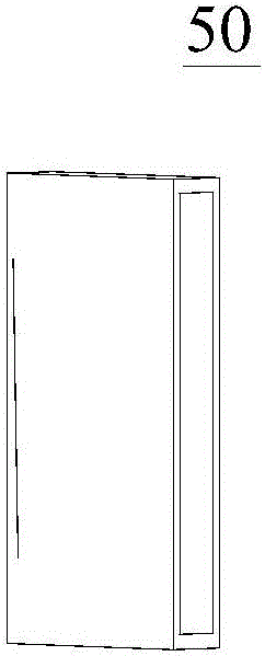
[0036] Attached below Figure 1 to Figure 6 The washing machine 100 according to the embodiment of the present invention will be described in detail.

[0037] The washing machine 100 according to the embodiment of the present invention includes: an outer cylinder 10, an inner cylinder 20, a plurality of water passage plates 30, a pulsator plate 40 and a plurality of floating blocks 50, the inner cylinder 20 is arranged in the outer cylinder 10 and is connected to the outer cylinder. 10 are arranged at intervals, a plurality of w...


PUM


Abstract

The invention discloses a washing machine which comprises an outer cylinder, an inner cylinder, a plurality of water flow passage plates, an impeller disk and a plurality of floating blocks. The inner cylinder is arranged in the outer cylinder and spaced apart from the outer cylinder. The water flow passage plates are spaced apart along the circumference of the inner cylinder. Each of the water flow passage plates and an inner wall of the inner cylinder limit a water flow passage. Each of the water flow passage plates is provided with a plurality of sprays arranged along its length. The impeller disk is rotatably provided at the bottom of the inner cylinder. A water exclusive chamber is defined between the impeller disk and the bottom of the inner cylinder. One side of the impeller disk facing the water exclusive chamber is provided with a water drainage rib. A plurality of floating blocks is movably provided on one side of the water flow passage plates facing away from the water flow passage to open and close the corresponding water sprinklers according to the water level of the inner cylinder. The washing machine improves the strength and the amount of the jet spray water flow, improves the washing ratio of the washing machine, and reduces the washing water amount.

Description

technical field [0001] The invention relates to the technical field of household appliances, in particular to a washing machine. Background technique [0002] When washing clothes, the pulsator washing machine relies on the positive and negative rotation of the pulsator to form an alternating reciprocating water flow to wash the clothes. When washing the clothes, it is easy to cause the entanglement of the clothes, which not only affects the cleaning efficiency of the washing machine but also damages the clothes. In order to prevent the entanglement of the clothes, During the work of the pulsator washing machine, by setting the spray waterfall plate in the inner cylinder of the washing machine, the water flow is used to spray the waterfall from the top of the clothes to rinse the clothes. The pulsator washing machine in the related art has only one position to fix the spray waterfall mouth. When it is less, the water output of the waterfall outlet is small and the water outp...

Claims


Application Information

Patent Timeline
Patent Type & Authority Applications(China)
IPC IPC(8): D06F17/06D06F17/04D06F17/10D06F39/08
CPCD06F17/04D06F17/06D06F17/10D06F39/088Y02B40/00
Inventor 李磊邓德喜周鹏孔凡实张华周福昌
Owner WUXI LITTLE SWAN ELECTRIC CO LTD
Learn More