
A vehicle parking mechanism adapted to the driving direction of the vehicle

A vehicle driving direction, vehicle technology, applied in roads, buildings, restricted traffic and other directions, can solve problems such as damage, reduce renovation costs, interception function discounts, etc., to achieve the effect of easy stopping, good restraint effect, and short stopping time

Active Publication Date: 2018-10-19
南通卓效自动化有限公司
View PDF0 Cites 0 Cited by
  • Summary
  • Abstract
  • Description
  • Claims
  • Application Information

AI Technical Summary

Problems solved by technology

However, for some vehicles, after the tires are deflated, the vehicle can still drive. At this time, the interception function of the broken tire structure will be greatly reduced.
In addition, the traditional interception technology often only considers how to quickly and successfully block the vehicle, and does not consider how to minimize the damage to the vehicle during the interception process, so it is very necessary to design a mechanism that can replace the traditional tire breaking technology , which can successfully intercept and minimize the damage to the vehicle so that the secondary use of the vehicle can reduce the cost of renovation

Method used


Image

  • A vehicle parking mechanism adapted to the driving direction of the vehicle
  • A vehicle parking mechanism adapted to the driving direction of the vehicle
  • A vehicle parking mechanism adapted to the driving direction of the vehicle

Examples


Embodiment Construction

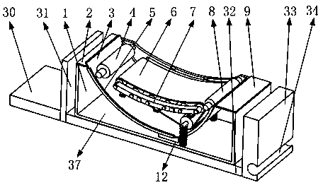
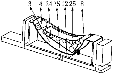
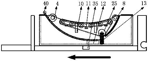
[0029] Such as figure 1 , 2 , shown in 12, it comprises binding mechanism 37, rotating base 38, binding mechanism rotating shaft 35, main rod, wherein binding mechanism rotating shaft 35 is installed in the middle of binding mechanism 37 lower sides, binding mechanism 37 is installed on rotating base 38 by binding mechanism rotating shaft 35 Above, a plurality of binding mechanisms 37 and their corresponding rotating bases 38 are installed side by side on the main pole.

[0030] Such as Figure 9 As shown, the above-mentioned rotating base 38 includes a front flap 30, a front vertical plate 31, a bottom plate 32, a rear vertical plate 33, a clamping hole 34, and a binding mechanism rotation hole 36, wherein the front vertical plate 31 and the rear vertical plate 33 are installed on the bottom plate respectively. 32 two ends, the front flap 30 is installed on the front end of the front vertical plate 31, the rear end of the lower side of the rear vertical plate 33 has a horizon...


PUM


Abstract

The invention relates to the technical field of vehicle interception, in particular to a vehicle stopping device adapting to vehicle driving. The device comprises a constraint mechanism, a rotating base, a constraint mechanism rotating shaft and a main rod, wherein the rotating base is clamped onto the main rod through a clamp hole which is not sealed; when the rotating base receives certain force, the main rod can powerfully disengage from the notch position of the clamp hole; the constraint mechanism can realize the constraint effect on wheels; the sliding on the ground is realized under thevehicle body inertia effect; the contact area of the rotating base with the ground is greater than the contact area of the wheels with the ground, so that the vehicle parking time is shorter. When the blocked parking vehicle runs into the constraint mechanism, a certain deviation angle is realized; the designed constraint mechanism can realize the small-angle deviation to adapt to the wheel angledeviation so as to reach the best constraint effect. The wheel constraint mechanism is used for achieving the constraint effect on the wheels; an automobile can fast brake under the condition withoutautomobile damage; the goal of helping public security organizations stop illegal vehicles is achieved; the good use effect is achieved.

Description

Technical field [0001] The invention belongs to the technical field of vehicle blocking, and in particular relates to a vehicle stopping mechanism adapted to the driving direction of the vehicle. Background technique [0002] At present, tire breaking technology is often used in the technical field of automobile interception, and its key technology is how to break tires rapidly so that the tires can be deflated as fast as possible. However, after some vehicle tires are deflated, the vehicle can still travel, and the interception function played by the broken tire structure will be greatly reduced at this time. In addition, the traditional interception technology often only considers how to quickly and successfully block the vehicle, and does not consider how to minimize the damage to the vehicle during the interception process, so it is very necessary to design a mechanism that can replace the traditional tire breaking technology , which can not only successfully intercept ...

Claims


Application Information

Patent Timeline
Patent Type & Authority Patents(China)
IPC IPC(8): E01F13/12
CPCE01F13/12
Inventor 李永建
Owner 南通卓效自动化有限公司
Learn More