
Superfine particulate matter removal system and method

An ultra-fine particle removal technology, applied in the field of ultra-fine particles, droplet condensation and capture, which can solve problems such as emissions

Pending Publication Date: 2021-08-20
BEIJING SPC ENVIRONMENT PROTECTION TECH
View PDF0 Cites 0 Cited by
  • Summary
  • Abstract
  • Description
  • Claims
  • Application Information

AI Technical Summary

Problems solved by technology

Under the total amount control, although the total content of flue gas particles meets the national requirements, there are still a large number of ultrafine particles and liquid droplets that will cause smog to be discharged into the atmosphere

Method used


Image

  • Superfine particulate matter removal system and method
  • Superfine particulate matter removal system and method
  • Superfine particulate matter removal system and method

Examples


Embodiment Construction

[0029] In order to make the purpose, technical solution and advantages of the present invention clearer, the implementation manners of the present invention will be further described in detail below.

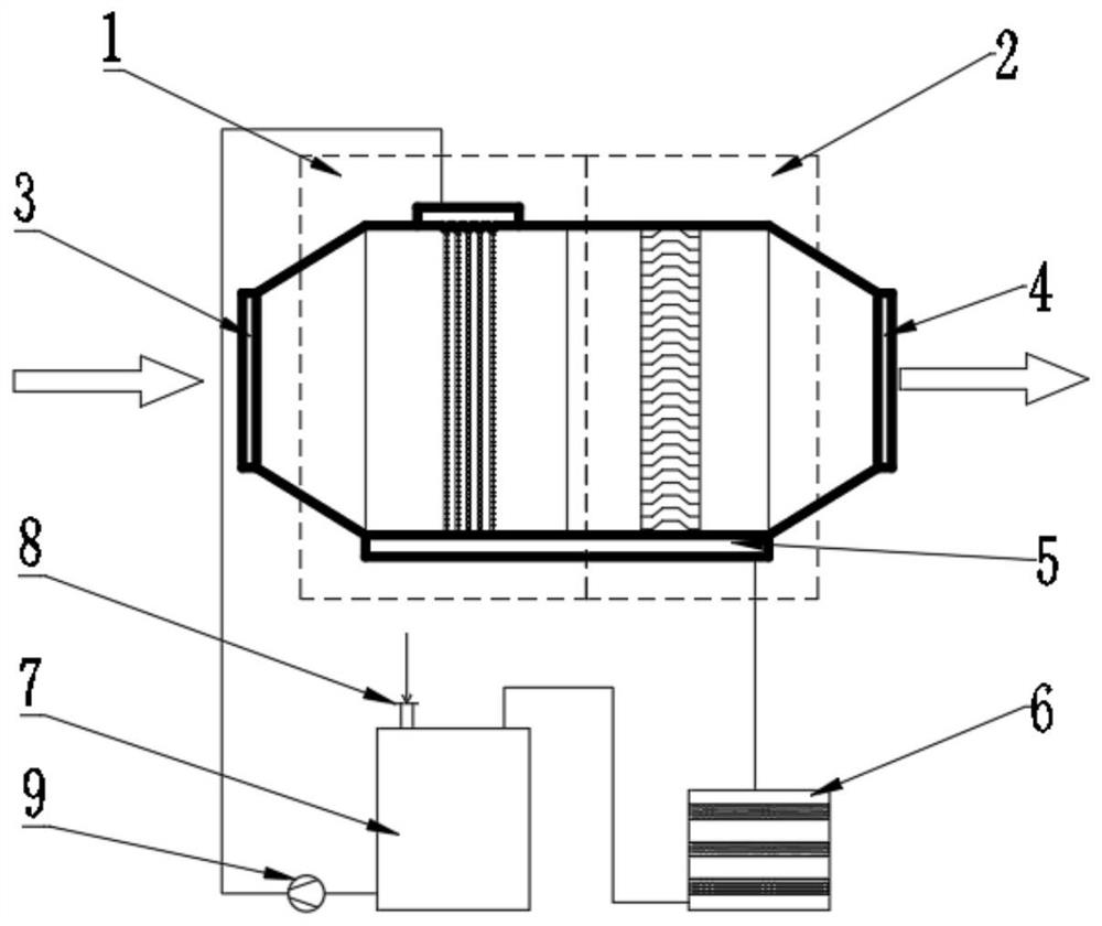
[0030] Such as figure 1 As shown, the ultrafine particle removal system of the present invention includes a condensation and interception area 1, a demisting area 2, a flue gas inlet 3, a flue gas outlet 4, a backflow collecting pan 5, a backflow filter 6, a circulating water tank 7, Neutralizing agent feeding box 8, circulating water pump 9. Condensation and interception zone 1, defogging zone 2, flue gas inlet 3, and flue gas outlet 4 together constitute the superfine particle coagulation and removal system. The reflux collection tray 5, the reflux filter 6, the circulating water tank 7, the neutralizer feeding port 8, and the circulating water pump 9 together constitute a reflux liquid purification circulation system. The flue gas enters the system through the flue gas inle...


PUM


Abstract

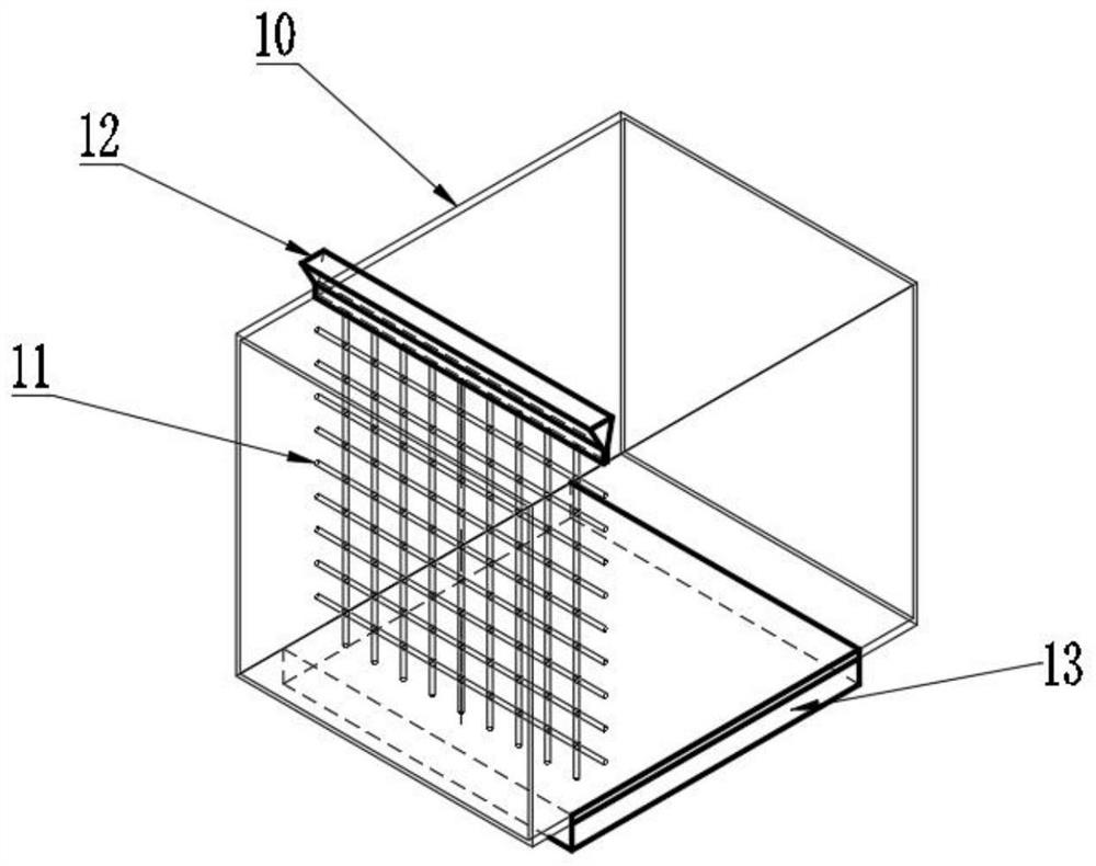
The invention discloses a superfine particulate matter removal system and method. The system comprises a coagulation interception area, a demisting area, a flue gas inlet, a flue gas outlet, a backflow collection disc, a recovery filter, a circulating water tank, a neutralizer feeding hole and a circulating water pump. When flue gas containing ultrafine particles and slurry drops passes through a removal device, the ultrafine particles and the slurry drops directly collide with uniform liquid films on a liquid film carrying screen to be converged, and a large number of ultrafine particles and slurry drops are intercepted or coagulated by the liquid films formed by surface tension; and the intercepted parts are discharged out of the system along with the reflux liquid, and the parts which are coagulated into large liquid drops and escaped are captured in the demisting area. According to the system, a plurality of layers of compact filtering liquid films are formed by utilizing the surface tension of the liquid films, so that superfine (PM2.5) particulate matters can be effectively prevented from escaping from slurry drops.

Description

technical field [0001] The invention belongs to the field of coagulation and trapping of ultrafine particles and droplets, and in particular relates to a system and method for removing ultrafine particles. Background technique [0002] At present, PM2.5 ultrafine particles are considered to mainly originate from motor vehicle (ship) emissions, power plant boilers, industrial furnaces and production processes, road and construction dust, straw burning, and civil scattered combustion. Among them, industrial boilers and kilns emit a large amount of flue gas, and the emission lasts for a long time, which is considered to be the main cause of smog. [0003] With the increasingly stringent environmental protection requirements, most coal-fired power plants in my country have completed ultra-low emission transformation. According to relevant regulations, the net flue gas particulate matter emission concentration of coal-fired power plants must be lower than 5mg / m 3 . The emission...

Claims


Application Information

Patent Timeline
IPC IPC(8): B01D47/02C02F9/04C02F103/18
CPCB01D47/022B01D47/024C02F1/001C02F1/66C02F2103/18B01D2247/04
Inventor 余志良赵玉何祥
Owner BEIJING SPC ENVIRONMENT PROTECTION TECH
Learn More