Garland X joint for steel structure building and mounting process of joint

A steel structure and node technology, applied in the direction of building and building structure, can solve problems such as high weather requirements, increased construction costs, building constraints, etc., to improve firmness and stability, prevent deformation, and improve support performance effect

Pending Publication Date: 2017-05-31
JIANGSU HUNING STEEL MECHANISM
View PDF5 Cites 5 Cited by
  • Summary
  • Abstract
  • Description
  • Claims
  • Application Information

AI Technical Summary

Problems solved by technology

At present, most of the buildings are made of reinforced concrete, which has a long construction period and high requirements on the weather. Once the temperature is low, the concrete is easy to freeze, and normal construction will not be possible, which will seriously affect the construction period of the project. At the same time, Reinforced concrete buildings require more materials and more labor, which increases the cost of construction
[0003] Most of the existing reinforced concrete buildings are painted on the surface of the building, or tiles are pasted on the surface. The paint is used for a limited time, and it is easy to fade after a long time, thus affecting its

Method used


Image

  • Garland X joint for steel structure building and mounting process of joint
  • Garland X joint for steel structure building and mounting process of joint

Examples


Embodiment 1

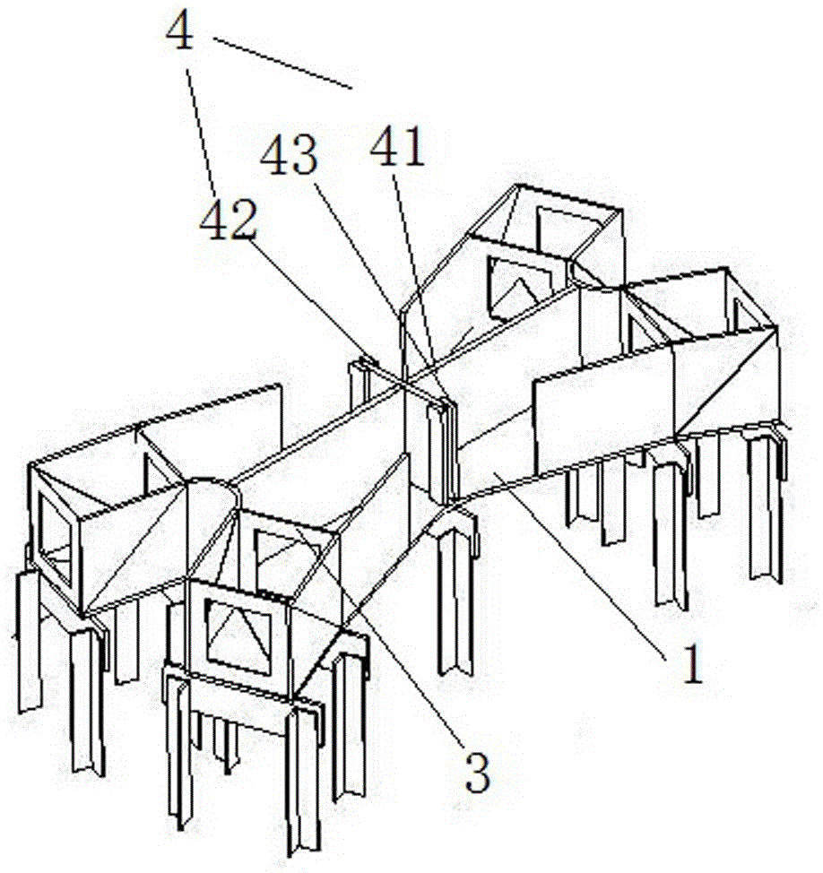
[0036] like figure 1 and figure 2 A garland X joint used in steel structure buildings shown is characterized in that it includes: a lower flange plate 1 and an upper flange plate 2, and the upper flange plate 2 is arranged on the bottom of the lower flange plate 1 above;

[0037] The relationship between the above components is as follows:

[0038] A stiffening plate 3 is provided between the upper flange plate 2 and the lower flange plate 1, a partition plate 4 is arranged in the middle of the stiffening plate 2, and the edge between the upper flange plate 2 and the lower flange plate 1 passes through The web 5 is connected.

[0039] Further, the stiffener 3 is polygonal, and an opening is provided in the middle.

[0040] Further, the stiffener 3 adopts a quadrangular shape, and it cooperates with the lower flange plate 1 and the upper flange plate 2 .

[0041] Further, the partition 4 is composed of a transverse partition 41 and a longitudinal partition 42, and the tra...

Embodiment 2

[0046] like figure 1 and figure 2A garland X joint used in steel structure buildings shown is characterized in that it includes: a lower flange plate 1 and an upper flange plate 2, and the upper flange plate 2 is arranged on the bottom of the lower flange plate 1 above;

[0047] The relationship between the above components is as follows:

[0048] A stiffening plate 3 is provided between the upper flange plate 2 and the lower flange plate 1, a partition plate 4 is arranged in the middle of the stiffening plate 2, and the edge between the upper flange plate 2 and the lower flange plate 1 passes through The web 5 is connected.

[0049] Further, the stiffener 3 is polygonal, and an opening is provided in the middle.

[0050] Further, the stiffener 3 adopts a quadrangular shape, and it cooperates with the lower flange plate 1 and the upper flange plate 2 .

[0051] Further, the partition 4 is composed of a transverse partition 41 and a longitudinal partition 42, and the tran...


PUM


Abstract

The invention discloses a garland X joint for a steel structure building. The garland X joint comprises a lower flange plate and an upper flange plate arranged above the lower flange plate, a stiffening plate is arranged between the upper flange plate and the lower flange plate, a partition plate is arranged in the middle of the stiffening plate, and edges of the upper flange plate and the lower flange plate are connected through a web plate. According to the garland X joint for the steel structure building, the partition plate and the stiffening plate are arranged between the lower flange plate and the upper flange plate to effectively connect the lower flange plate and the upper flange plate, excellent decoration functions are achieved as for the building industry, aesthetic effects are achieved, use firmness and stability of the X joint are greatly improved, deformation can be effectively prevented, and double functions can be further achieved.

Description

technical field [0001] The invention belongs to the field of production and manufacturing, in particular to a latte X node used in steel structure buildings and an installation process thereof. Background technique [0002] With the rapid development of social economy, all walks of life are constantly developing, and the pace of people's work and life is constantly accelerating. Both the production of enterprises and people's lives have been modernized and intelligent. The demand for all kinds of products is more and more high, and the construction industry is also the same. At present, most of the buildings are made of reinforced concrete, which has a long construction period and high requirements on the weather. Once the temperature is low, the concrete is easy to freeze, and normal construction will not be possible, which will seriously affect the construction period of the project. At the same time, Reinforced concrete buildings require more materials and more labor, wh...

Claims


Application Information

Patent Timeline
IPC IPC(8): E04B1/24
CPCE04B1/24E04B2001/2406
Inventor 万家福蔡蕾巫明杰葛方邹峰蒋飞张建新
Owner JIANGSU HUNING STEEL MECHANISM
Why Eureka
Try Eureka