Clamping fastening type wall panel

A wall panel and buckle-type technology, which is applied to building components, buildings, ceilings, etc., can solve the problems of inconvenient replacement, damage to wall panels, waste, etc., and achieve the effect of cost saving and overall weight reduction

Inactive Publication Date: 2017-05-31
浙江云时代光电股份有限公司
View PDF9 Cites 2 Cited by
  • Summary
  • Abstract
  • Description
  • Claims
  • Application Information

AI Technical Summary

Problems solved by technology

[0002] The existing integrated ceiling wall panels are usually fixedly connected by means of male and female groove sockets. This connection method is inconvenient to replace whe

Method used


Image

  • Clamping fastening type wall panel
  • Clamping fastening type wall panel
  • Clamping fastening type wall panel

Examples


Example Embodiment

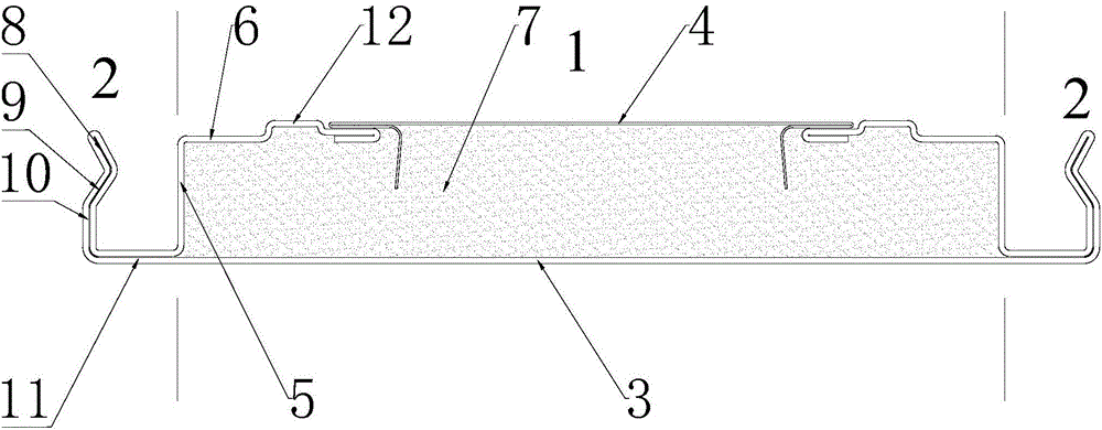
[0018] Example one, combination figure 1 , The snap-in wall panel involved in this embodiment is a flat seam wall panel, which includes a wall panel body 1 and a connecting portion 2; the wall panel body 1 includes a panel 3, a back board 4, a vertical board 5, and a back board support portion 6. And the filling layer 7; the connecting portion 2 includes a first bending section 8, a second bending section 9 and a third bending section 10; the connecting portion 2 also includes a connecting bending section 11 with the wall panel body; the third bending The section 10 is perpendicular to the connecting section 11; the second bending section 9 is bent in the direction of the wall panel body 1; the first bending section 8 is reversely bent relative to the second bending section 9. The back plate supporting portion 6 is provided with a protrusion 12; the free end of the end of the back plate supporting portion 6 is bent inward. The panel 3, the connecting part 2, the vertical plate ...

Example Embodiment

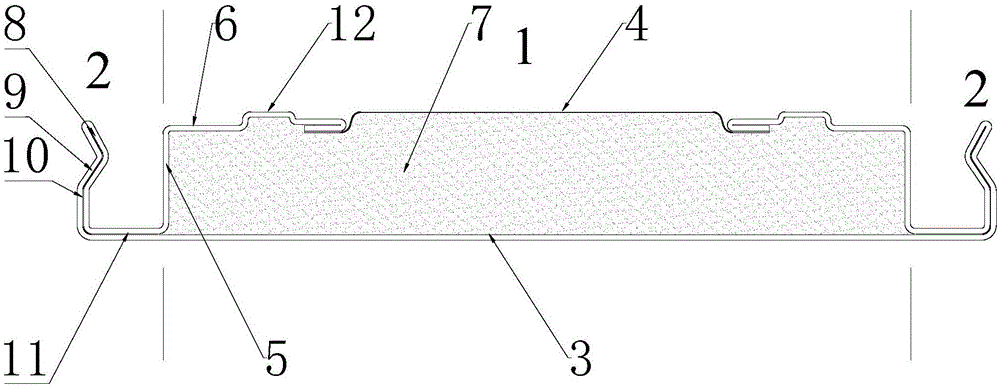
[0020] Example two, reference figure 2 The difference between the snap-in wall panel involved in this embodiment and the embodiment is that the backplane 2 used is aluminum foil paper. In the production process of the snap-on wall panel involved in this embodiment, the wall panel body 1 expands when polyurethane is foamed, and combined with the crawler-type production line, the thickness of the snap-on wall panel involved in this embodiment can be controlled. The foaming of polyurethane enables the two ends of the aluminum foil paper to be fixed under the back plate support 6.

Example Embodiment

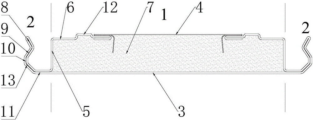
[0021] Example three, reference image 3 The snap-in wall panel involved in this embodiment is a V-shaped wall panel. The difference from the first embodiment is that the connecting portion 2 further includes a fourth bending section 13, and the first bending section 8 and the connecting section 11 pass through the The four bending sections 13 are connected. The arrangement of the fourth bending section 13 enables the two adjacent snap-in wall panels to form a V-shaped groove during assembly of the snap-in wall panel in this embodiment.


PUM


Abstract

The invention discloses a clamping fastening type wall panel which comprises a wall panel body and connection portions. The wall panel body comprises a panel, a back plate, a vertical plate, a back plate supporting portion and a filling layer. Each connection portion comprises a first bending section, a second bending section, a third bending section and a connection section, wherein the connection section is used for connection with the wall panel body, the second bending section is bent towards the direction of the wall panel body, and the third bending section is bent opposite to the second bending section. The panel, the back plate, the connection portions, the vertical plate and the back plate supporting portion are made by integral bending of a metal sheet. The clamping fastening type wall panel can be closely matched with special fasteners in assembly to realize well fixing of the clamping fastening type wall panel, the wall panel is protected from damages in replacement and demounting, and the demounted wall panel can be recycled, so that cost is saved. In addition, due to adoption of an aluminum sheet or aluminum foil as the back plate, integral weight of the wall panel can be reduced.

Description

technical field [0001] The invention relates to the technical field of wall panels, in particular to a buckle-type wall panel. Background technique [0002] The existing integrated ceiling wall panels are usually fixedly connected by means of male and female groove sockets. This connection method is inconvenient to replace when the wall panels cannot meet the visual requirements or the wall panels are damaged, and the rest will be damaged during disassembly. Wall panels cannot be reused, causing waste. Contents of the invention [0003] One of the purposes of the present invention is to provide a buckle-type wall panel, which can be assembled more conveniently, can not damage the wall panel when disassembled, can be reused, and can effectively save the user's expenditure cost. [0004] Another object of the present invention is to provide a buckle-type wall panel, which can reduce the overall weight of the entire wall panel. [0005] In order to solve the above technical...

Claims


Application Information

Patent Timeline
IPC IPC(8): E04B9/04
CPCE04B9/0435E04B9/0457
Inventor 周金龙
Owner 浙江云时代光电股份有限公司
Why Eureka
Try Eureka