Floor fan device

A floor fan and movable ground technology, applied in coupling devices, parts of pumping devices for elastic fluids, electrical components, etc., can solve the problems of inconvenience, insufficient length, easy tripping, etc., and achieve the effect of convenient use

Active Publication Date: 2017-05-31
安徽明亮面业股份有限公司
View PDF7 Cites 0 Cited by
  • Summary
  • Abstract
  • Description
  • Claims
  • Application Information

AI Technical Summary

Problems solved by technology

[0002] A fan refers to an appliance used to generate wind to keep cool in hot weather. It is driven by electricity to generate airflow. There are many types of fans, including floor-standing and hanging types. Floor-standing ones can usually be placed anywhere and can blow the human body. The electric wires of the floor fans are fixed in length, so people need to change their farther positions because the length is not enough and they cannot move there, or because they are too long so that people are easy to trip when passing by the fan when walking. causing inconvenience to people

Method used


Image

  • Floor fan device
  • Floor fan device
  • Floor fan device

Examples


Embodiment Construction

[0019] All features disclosed in this specification, or steps in all methods or processes disclosed, may be combined in any manner, except for mutually exclusive features and / or steps.

[0020] Any feature disclosed in this specification (including any appended claims, abstract and drawings), unless expressly stated otherwise, may be replaced by alternative features which are equivalent or serve a similar purpose. That is, unless expressly stated otherwise, each feature is one example only of a series of equivalent or similar features.

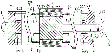
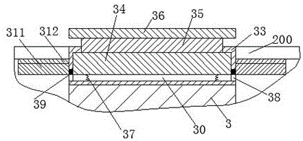
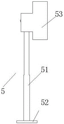
[0021] Such as Figure 1-3 As shown, a floor fan device of the present invention includes a main power supply line 1 for connecting to the mains, a floor fan 5 for accelerating air flow, and a reduction mechanism 2, and the floor fan 5 includes a height-adjustable support rod 51 , the lower end of the support rod 51 is fixedly provided with a bottom tray 52, the upper end of the support rod 51 is provided with a fan head 53, and the fan head ...


PUM


Abstract

A floor fan device comprises a main energization wire for being connected with a mains supply, a floor fan for accelerating air flowing, and a reduction mechanism. The floor fan comprises a height-adjustable support rod. A bottom tray is fixedly arranged at the lower end of the support rod. A fan head is arranged at the upper end of the support rod. A main energization part and a secondary energization part are arranged at the two ends of the reduction mechanism separately. A moving cavity extending left and right is formed in the reduction mechanism. The main energization part and the secondary energization part are internally provided with a main energization groove and a secondary energization groove correspondingly, and inlets of the main energization groove and the secondary energization groove face the moving cavity. The upper end wall and the lower end wall of the reduction mechanism are each provided with a guide connecting countersunk groove communicating with the moving cavity. A movable access head is installed in the moving cavity in a left-right movable mode, guide connecting plates are fixedly arranged on the upper side and the lower side of the movable access head correspondingly, and the guide connecting plates are poked into the guide connecting countersunk grooves and are flush with the outer end walls of the reduction mechanism.

Description

technical field [0001] The invention relates to the field of fan facilities, in particular to a floor fan device. Background technique [0002] A fan refers to an appliance used to generate wind to keep cool in hot weather. It is driven by electricity to generate airflow. There are many types of fans, including floor-standing and hanging types. Floor-standing ones can usually be placed anywhere and can blow the human body. The electric wires of the floor fans are fixed in length, so people need to change their farther positions because the length is not enough and they cannot move there, or because they are too long so that people are easy to trip when passing by the fan when walking. thereby causing inconvenience to people. Contents of the invention [0003] The object of the present invention is to provide a floor fan device and its use method, which can overcome the above-mentioned defects of the prior art. [0004] According to the present invention, a floor fan devi...

Claims


Application Information

Patent Timeline
IPC IPC(8): F04D29/00H01R31/06
CPCF04D29/002H01R31/06
Inventor 马浩晓
Owner 安徽明亮面业股份有限公司
Why Eureka
Try Eureka