
Clamping device

A clamping device and clamping piece technology, applied in the direction of friction clamping of detachable fasteners, connecting components, mechanical equipment, etc., can solve problems such as hidden dangers, inconvenient replacement, inconvenient replacement of batteries, etc., and achieve convenient operation. Effect

Active Publication Date: 2017-05-31
HANGCHA GRP
View PDF6 Cites 0 Cited by
  • Summary
  • Abstract
  • Description
  • Claims
  • Application Information

AI Technical Summary

Problems solved by technology

[0003] 1. Bolts and limit blocks are used to connect the upper and lower parts under force, which can only provide a small force in terms of force;
[0004] 2. It is inconvenient to replace the battery. Generally, vehicles with sideways batteries are frequently replaced. For devices fixed with bolts, it is inconvenient to replace;
[0005] 3. The left and right limit is generally fixed by the side door, and then the side door is added with a buffer block to limit the left and right movement of the battery. This kind of fixing method, because there must be a certain gap when installing the door, so the battery cannot be completely restricted, and there are certain safety hazards

Method used


Image

  • Clamping device
  • Clamping device
  • Clamping device

Examples


Embodiment Construction

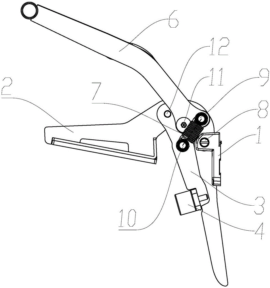
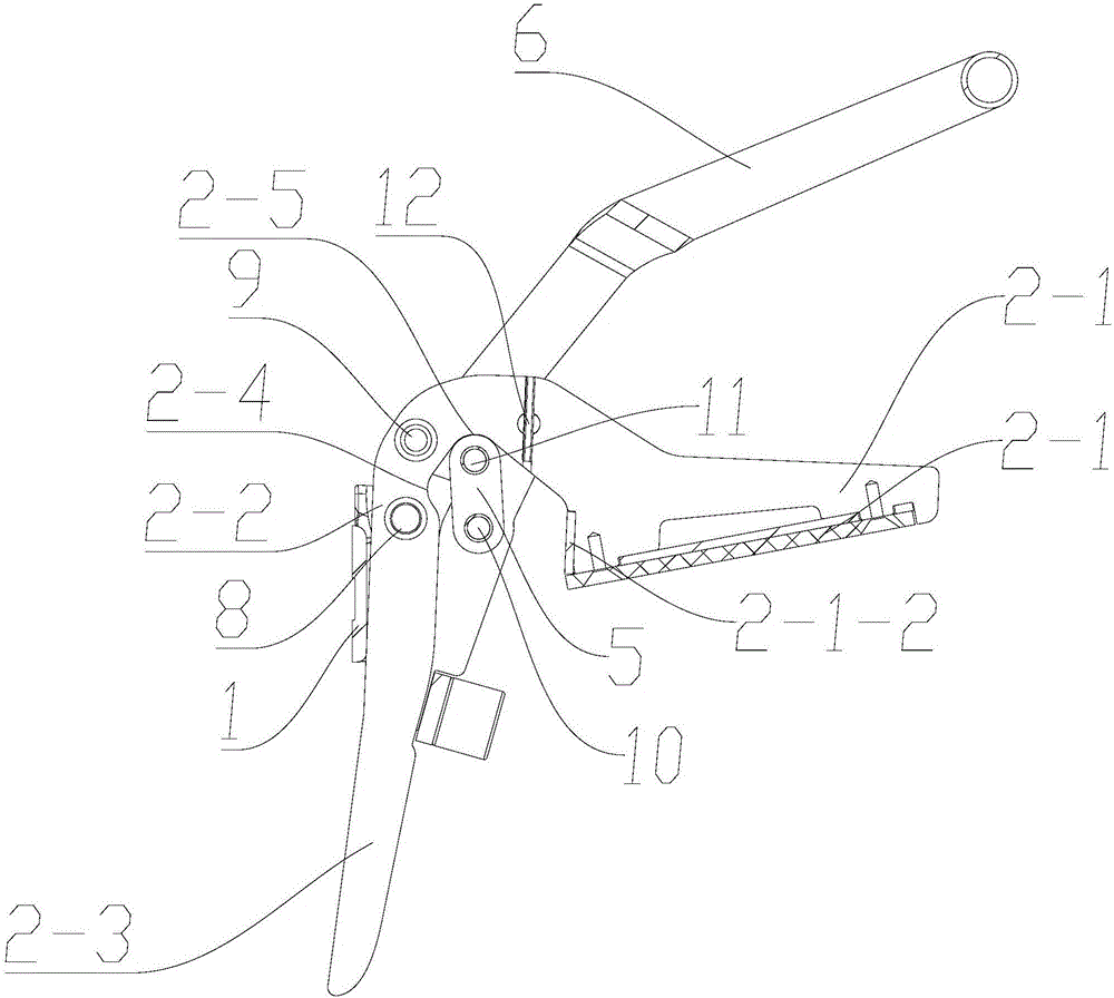
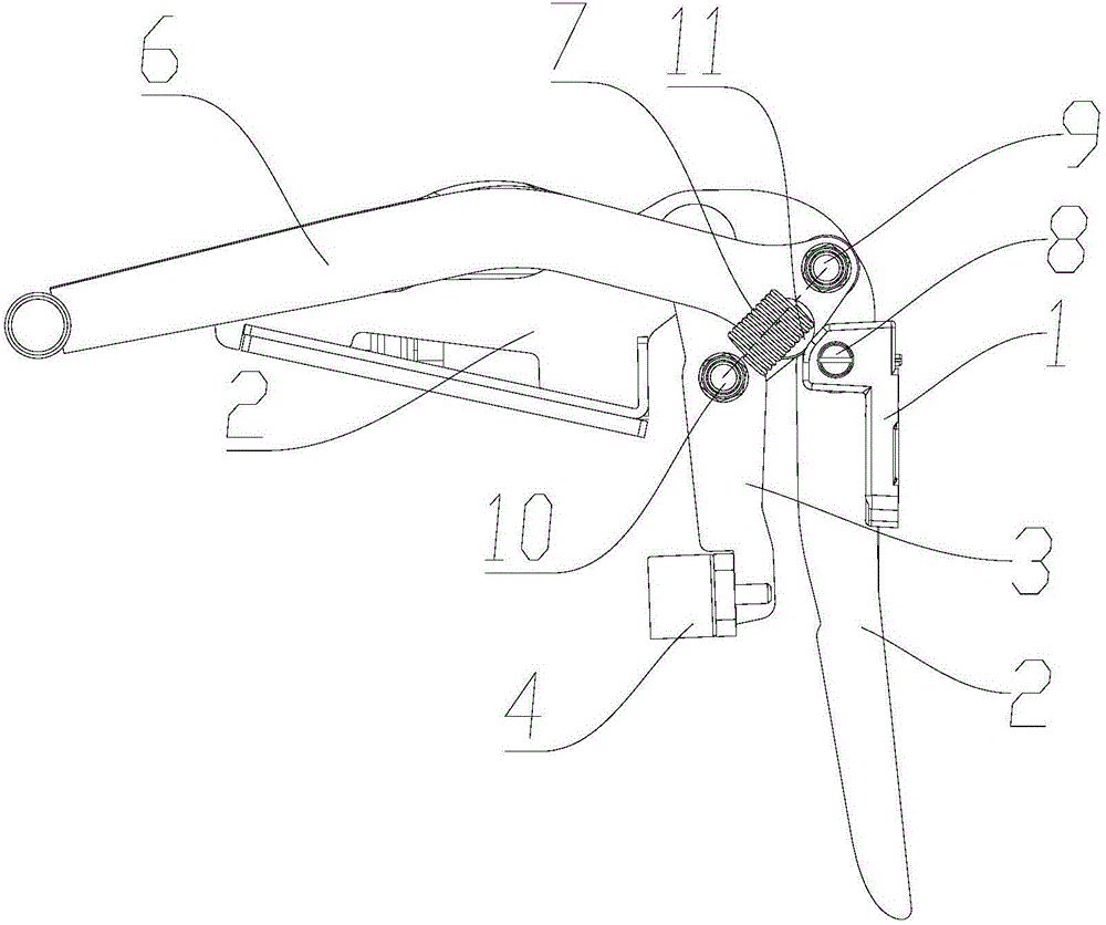
[0022] Such as Figure 1 to Figure 6 As shown, this embodiment is a clamping device for battery lateral movement, including a mounting base 1, a clamping part I2 and a clamping part II3, wherein the clamping part I2 is in the shape of a 7, and the clamping part I2 is from top to bottom The bottom is divided into guide clamping section 2-1, rotating shaft installation section 2-3 and limiting section 2-3 in turn.

[0023] In this example, the mounting base 1 is installed on the vehicle frame via bolts, and the clamping part I2 is rotatably connected to the mounting base 1 through the rotating shaft A8 of the rotating shaft mounting section 2-2 installed thereon. When there is no external force, the guide clamping section 2-1 rotates downward around the rotating shaft A8 until the limit section touches the vehicle frame. At this time, the direction of the guide clamping section 2-1 facing the battery has an inclined upward slope, forming The guide portion 2-1-1; the clamping po...


PUM


Abstract

The invention relates to a clamping device. According to the purposes, the clamping device is safe, reliable and convenient to use. According to the technical scheme, the clamping device is characterized by comprising an installation seat, a clamping piece I and a clamping piece II; the clamping piece I is in the shape of an Arabic number '7'; a guiding clamping section, a rotating shaft installation section and a limiting section are sequentially installed from one end to the other end of the clamping piece I, wherein the guiding clamping section is provided with a guiding part and a clamping part, and the clamping piece I is rotationally connected to the installation seat through a rotating shaft A of the rotating shaft installation section; the upper end of the clamping piece II is rotationally connected to the clamping piece I through a rotating shaft O, and the lower end of the clamping piece II is provided with a clamping block; and an automatic locking mechanism capable of driving the clamping piece II to rotate around the rotating shaft O and locking the relative position of the clamping piece II and the clamping piece I is arranged between the clamping piece I and the clamping piece II.

Description

technical field [0001] The invention relates to a clamping device. Background technique [0002] The battery of the traditional electric pallet truck is fixed by sideways movement. Generally, bolts and limit blocks are used to limit the up and down movement, and the side door is used to fix the side door to limit the left and right movement. This method has the following problems: [0003] 1. Bolts and limit blocks are used to connect the upper and lower parts under force, which can only provide a small force in terms of force; [0004] 2. It is inconvenient to replace the battery. Generally, vehicles with sideways batteries are frequently replaced. For devices fixed with bolts, it is inconvenient to replace; [0005] 3. The left and right limit is generally fixed by the side door, and then the side door is added with a buffer block to limit the left and right movement of the battery. This fixing method, because there must be a certain gap when installing the door, so the b...

Claims


Application Information

Patent Timeline
Patent Type & Authority Applications(China)
IPC IPC(8): F16B2/06
CPCF16B2/06
Inventor 张晓录徐翔李克忠
Owner HANGCHA GRP
Learn More