Fan lamp of invisible fan blade

A technology of invisible fans and fan lamps, which is applied to the components of lighting devices, components of pumping devices for elastic fluids, lighting and heating equipment, etc. It can solve the problems of lack of motors and use restrictions, and achieve small size , fast rotation response and simple structure

Pending Publication Date: 2017-05-31
江门市动盈科技有限公司
View PDF10 Cites 1 Cited by
  • Summary
  • Abstract
  • Description
  • Claims
  • Application Information

AI Technical Summary

Problems solved by technology

[0004] Recently, with the development of society and the rise of the lighting industry, in order to adapt to the pursuit of the younger generation, fan lights have gradually appeared invisible fan lights, such as the patent No. 201520361316. The fan light is that when the motor is turned off, the fan blades shrink back. Due to the cover of the lighting, the fan blades are usually invisible; but under the rotation of the motor, due to the centrifugal force and power, the fan blades will automatically expand outwards. And generate wind power to form a wind wheel state, but the invisible fan light with this structure can only be used to supply air in one direction, which has a large limitation in use, and does not have the ability to rotate the motor whether it is forward or reverse Expand the function of generating wind force

Method used


Image

  • Fan lamp of invisible fan blade
  • Fan lamp of invisible fan blade
  • Fan lamp of invisible fan blade

Examples


Embodiment 1

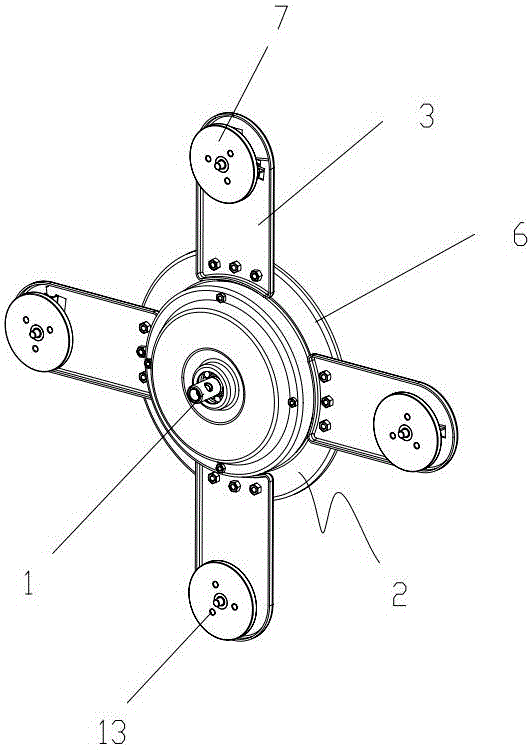
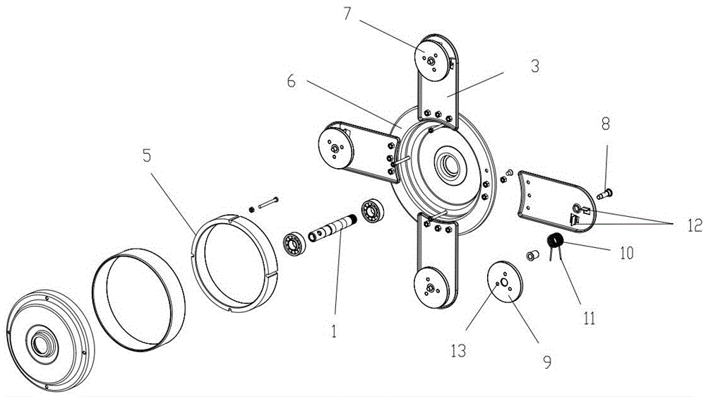
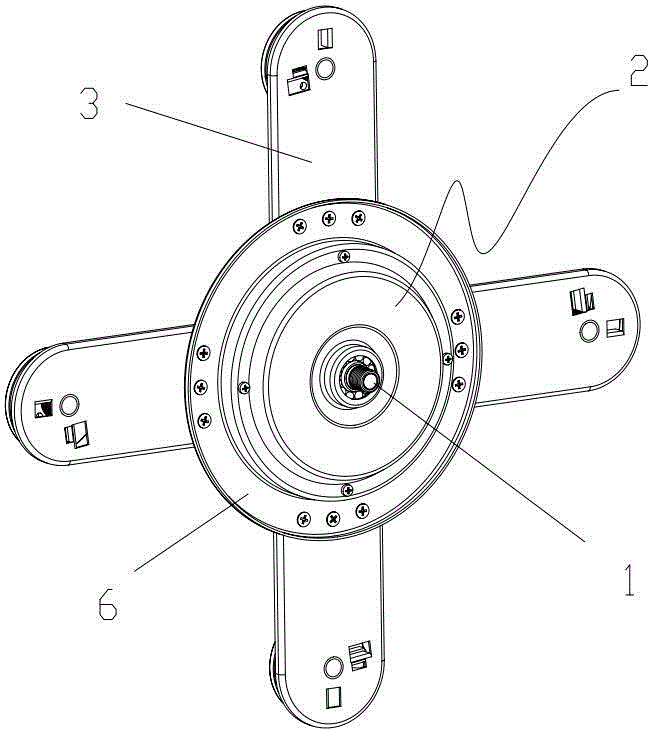
[0016] A fan lamp with invisible fan blades described in this embodiment 1, such as figure 1 , figure 2 and image 3 As shown, it includes a motor center shaft 1 with one end fixed to the ceiling and the other end fixed to the lighting, and also includes a motor 2 connected to the motor center shaft, four fan blade connection disks 3 fixedly connected to the motor, and a separate fan blade. The connecting plate connects and installs the fan blades that can be unfolded or folded. The motor includes a stator fixed on the central axis of the motor, a rotor 5 arranged around the stator, and a rotor casing 6 fixed and fitted with the rotor. The fan blade connecting plate One end is evenly distributed and fixed on the rotor casing with the central axis of the motor as the center, and the other end of the fan blade connecting plate is provided with a fan blade centrifugal expansion device 7 that is rotated by the motor to expand the fan blade; the fan blade centrifugal expansion de...


PUM


Abstract

The invention discloses a fan lamp of an invisible fan blade. The fan lamp comprises a motor center shaft, a motor, a plurality of fan blade connecting discs and a plurality of fan blade bodies, wherein the motor is installed on the motor center shaft in a connected mode, and the fan blade connecting discs and the fan blade bodies are fixedly connected with the motor; the motor comprises a stator, a rotor and a rotor outer shell, wherein the stator is fixedly installed on the motor center shaft, the rotor is installed on the stator in a surrounding mode, and the rotor outer shell is installed on the rotor in a fixedly-matched mode; and a blade centrifugal spreading unit which enables the fan blade bodies to spread through rotating of the motor is installed at the other end of each fan blade connecting disc, and each blade centrifugal spreading unit comprises a fixed shaft fixed to the corresponding fan blade connecting disc, a fan blade disc which rotates around the corresponding fixed shaft, a torsion spring which is sleeved on the corresponding fixed shaft and jointly rotates along with the corresponding fan blade disc, and torsion rods which stretch out of the two ends of the corresponding torsion spring; and by installing limiting torsion rod rotating angles on the fan blade connecting discs, limiting blocks achieves the condition that when the motor rotates positively or negatively, the fan blade bodies all spread, through the blade centrifugal spreading units, the fan blade bodies can spread to achieve the air supplying function when the motor rotates positively or negatively, and when the motor is outage, the fan blade bodies can be drawn back and hidden in a lamp shade.

Description

technical field [0001] The invention relates to the structural field of a fan lamp, in particular to a fan lamp which is installed and hung on the ceiling for lighting and blowing, and can expand or fold invisible fan blades when the motor rotates forward or reverse. Background technique [0002] At present, ceiling fans are electrical appliances that are often installed and used in people's homes, and they are mostly installed on the ceiling of the roof; the existing fan lights for lighting and blowing on the ceiling are driven by a motor to drive the fan blades to rotate, and one end of the central shaft of the motor is fixed to the ceiling. The other end is fixed on the top of the lamp, the motor is arranged above the lamp, and the motor drives the fan blade. [0003] At present, the fan blades of traditional fan lights are fixed to the motor. Even when the fan is turned off, you can see the fan blades that are greatly expanded, that is, the fan blades of the fan light ar...

Claims


Application Information

Patent Timeline
Patent Type & Authority Applications(China)
IPC IPC(8): F21V33/00F04D25/08F04D29/26
CPCF04D25/0606F04D25/088F04D29/26F21V33/0096
Inventor 赵健全
Owner 江门市动盈科技有限公司
Why Eureka
Try Eureka