Temperature adjustable solar heating device
A heating device and solar energy technology, applied in the field of heating, can solve the problems that the temperature of heat energy cannot reach the required temperature, large energy, and the outlet temperature cannot be adjusted according to needs, etc., and achieve the effect of improving heat conversion efficiency
- Summary
- Abstract
- Description
- Claims
- Application Information
AI Technical Summary
Problems solved by technology
Method used
Image

Examples
Embodiment Construction
[0019] The technical solutions of the present invention will be further described below in conjunction with the accompanying drawings and through specific implementation methods.
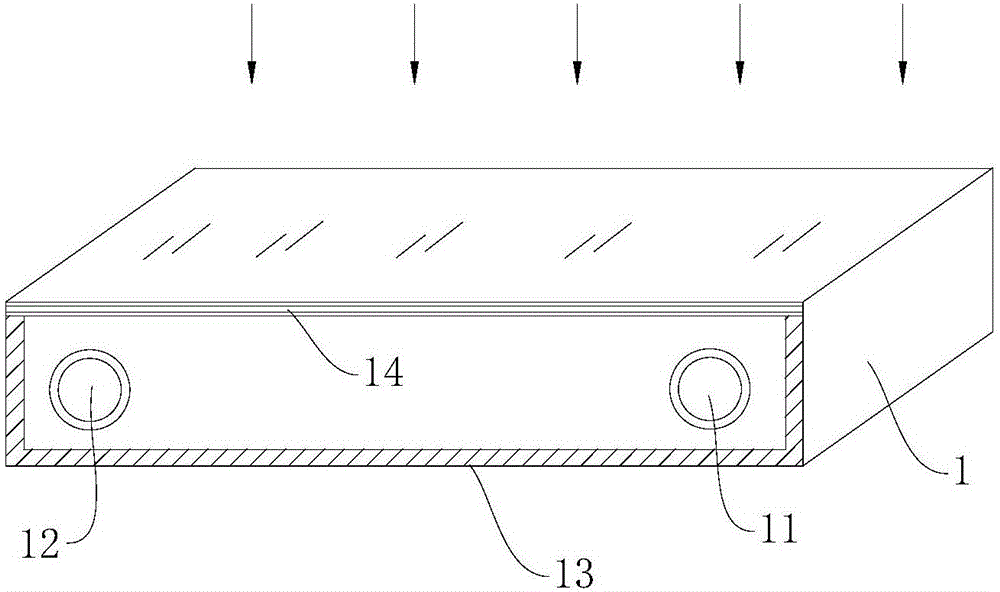
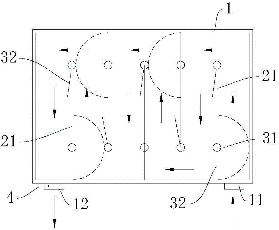
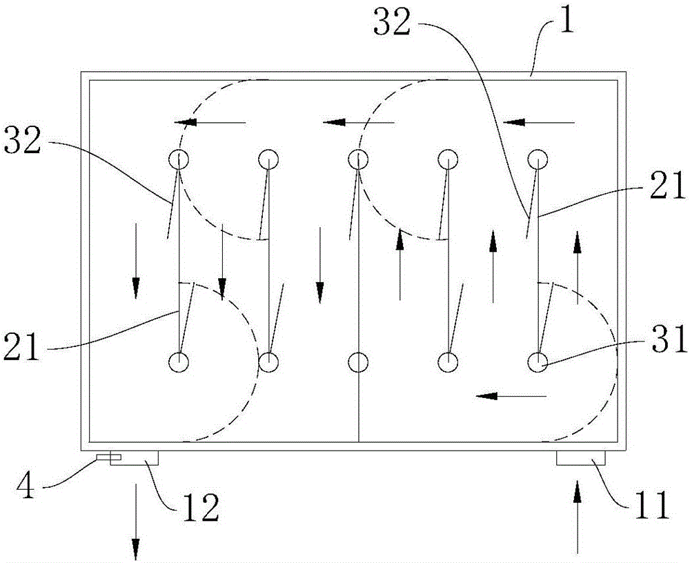
[0020] combine Figure 1 to Figure 3 As shown, this embodiment provides a temperature-adjustable solar heating device, which includes a heat-insulating and heat-absorbing box 1, a heating flow channel arranged in the heat-insulating and heat-absorbing box 1, and a heating flow channel arranged through the An input port 11 and an output port 12 for heating medium to flow in and out, and a flow guiding mechanism that cooperates with the heating flow channel to form different heating path lengths, and the flow guiding mechanism is connected with an external electric control device.
[0021] Specifically, in this embodiment, a plurality of partitions 21 are arranged in parallel and at intervals in the cavity of the heat-preserving and heat-absorbing box 1, and the two ends of the plurality of partitions...
PUM
 Abstract
Description
Claims
Application Information
PatSnap Eureka turns technology decisions into work you can execute. Powered by our Innovation Knowledge Graph, it runs expert workflows across engineering, life sciences, materials and intellectual property. Get your review-ready output in minutes.


