
Solar stepped heating high-temperature heat collecting system based on molten salt heat transmission and heat accumulation

A technology of cascade heating and solar energy, applied in the field of energy storage, can solve the problems of increased heat loss, reduced thermal conversion efficiency of the system, and decreased thermal efficiency, and achieves the effect of preventing excessive heat loss and improving thermal conversion efficiency.

Inactive Publication Date: 2016-01-06
百吉瑞(天津)新能源有限公司
View PDF2 Cites 12 Cited by
  • Summary
  • Abstract
  • Description
  • Claims
  • Application Information

AI Technical Summary

Problems solved by technology

As the working temperature of the collector tube increases, its heat loss also increases
In particular, when the working temperature of the heat collecting tube exceeds 400°C, the thermal efficiency of the system drops rapidly, and the life of the heat collecting tube also decreases
If the working temperature of the heat collecting tube is lowered within the range that ensures the heat loss of the heat collecting tube is small, the heat conversion efficiency of the system will also be reduced.

Method used


Image

  • Solar stepped heating high-temperature heat collecting system based on molten salt heat transmission and heat accumulation
  • Solar stepped heating high-temperature heat collecting system based on molten salt heat transmission and heat accumulation
  • Solar stepped heating high-temperature heat collecting system based on molten salt heat transmission and heat accumulation

Examples


Embodiment 1

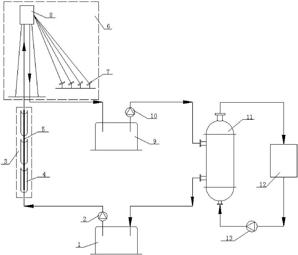
[0025] Embodiment 1: The high-temperature heat collection section 6 is a tower system composed of heliostats and tower top receivers

[0026] Such as figure 1 As shown, this embodiment includes: low temperature salt storage tank 1, low temperature molten salt pump 3, trough parabolic mirror 4, heat collecting tube 5, heliostat (concentrator 7), tower top receiver (receiver 8), High-temperature salt storage tank 9 , high-temperature molten salt pump 10 , molten salt-working medium heat exchanger 11 , heat-using equipment 12 and circulation pump 13 .

[0027] The low temperature salt storage tank 1, low temperature molten salt pump 2, trough parabolic mirror 4, heat collecting tube 5, heliostat 7, tower top receiver 8, high temperature salt storage tank 9, high temperature molten salt pump 10 and molten salt - The working medium heat exchanger 11 forms a molten salt circulation loop.

[0028] The molten salt-working medium heat exchanger 11, the heat utilization equipment 12 a...

Embodiment 2

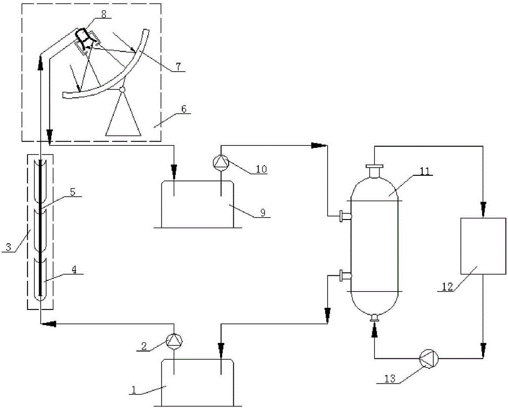
[0030] Embodiment 2: The high-temperature heat collection section 6 is a dish system composed of heliostats and tower top receivers

[0031] Such as figure 2 As shown, this embodiment includes: a low temperature salt storage tank 1, a low temperature molten salt pump 2, a trough parabolic mirror 4, a heat collecting tube 5, a dish parabolic mirror (concentrator 7), a cavity receiver (receiver 8) , high-temperature salt storage tank 9, high-temperature molten salt pump 10, molten salt-working medium heat exchanger 11, heat-using equipment 12 and circulation pump 13.

[0032] The low temperature salt storage tank 1, the low temperature molten salt pump 2, the trough parabolic mirror 4, the heat collecting tube 5, the dish parabolic mirror 7, the cavity receiver 8, the high temperature salt storage tank 9, the high temperature molten salt pump 10 and the melting The salt-working medium heat exchanger 11 forms a molten salt circulation loop.

[0033] The molten salt-working med...

Embodiment 3

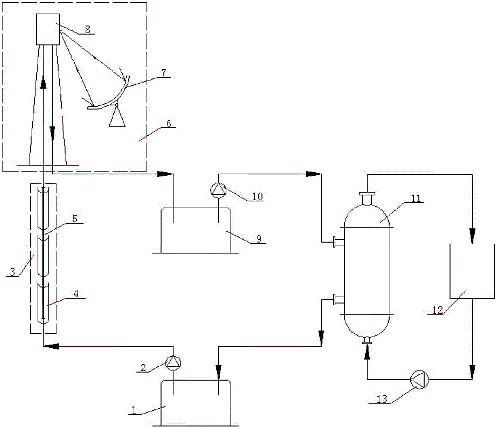
[0035] Embodiment 3: The high-temperature heat collection section 6 is a dish tower system composed of heliostats and tower top receivers

[0036] Such as image 3 As shown, this embodiment includes: a low-temperature salt storage tank 1, a low-temperature molten salt pump 2, a trough parabolic mirror 4, a heat collecting tube 5, a dish parabolic mirror (concentrator 7), and a tower top receiver (receiver 8) , high-temperature salt storage tank 9, high-temperature molten salt pump 10, molten salt-working medium heat exchanger 11, heat-using equipment 12 and circulation pump 13.

[0037] The low temperature salt storage tank 1, the low temperature molten salt pump 2, the trough parabolic mirror 4, the heat collecting tube 5, the dish parabolic mirror 7, the tower top receiver 8, the high temperature salt storage tank 9, the high temperature molten salt pump 10 and the melting The salt-working medium heat exchanger 11 forms a molten salt circulation loop.

[0038] The molten s...


PUM


Abstract

The invention discloses a solar stepped heating high-temperature heat collecting system based on molten salt heat transmission and heat accumulation. The system comprises a low-temperature salt storage tank (1), a high-temperature salt storage tank (9), a low-temperature molten salt pump (2), a high-temperature molten salt pump (10), a medium-temperature heat collecting section (3), a high-temperature heat collecting section (6), a molten salt-working medium heat exchanger (11), heat use equipment (12) and a circulating pump (13). The medium-temperature heat collecting section (3) consists of a groove type paraboloid mirror (4) and a heat collecting tube (5); the molten salt temperature in the heat collecting tube (5) is lower than 400 DEG C; the high-temperature heat collecting section (6) consists of a condenser (7) and a receiver; and the molten salt temperature in the receiver (8) can reach above 550 DEG C. The molten salt operation temperature of the medium-temperature heat collecting section (3) is controlled within 400 DEG C, so that the heat loss of the heat collecting tube (5) is in a smaller range; and as the high-temperature heat collecting section (6) is added, the molten salt operation temperature reaches above 550 DEG C, and the heat conversion efficiency of the system is correspondingly improved.

Description

technical field [0001] The invention belongs to the technical field of energy storage, and in particular relates to a solar cascade heating high-temperature heat collection system based on molten salt heat transfer and heat storage. Background technique [0002] Solar thermal utilization technology is a clean energy utilization technology that directly converts the sun's radiant energy into heat energy for utilization. There are mainly three types of solar thermal utilization systems: trough type, tower type and dish type. The trough solar thermal utilization system belongs to the medium temperature system, which uses a trough parabolic concentrating collector, usually the concentration ratio is between 10 and 100, and the operating temperature of the working medium in the collector generally does not exceed 600°C. Tower-type solar thermal utilization system is a high-temperature system, which uses a large number of heliostats to reflect solar heat radiation to its receiver...

Claims


Application Information

Patent Timeline
Patent Type & Authority Applications(China)
IPC IPC(8): F24J2/04F24J2/30F24J2/34F24J2/12F24S10/30F24S23/71
CPCY02E10/44
Inventor 马重芳吴玉庭刘斌
Owner 百吉瑞(天津)新能源有限公司
Learn More