a marching fixer

A technology of marching fixer and fixing pin, which is applied to the fixation of guns, weapon accessories, offensive equipment, etc., can solve the problems of reducing the mobility of equipment and complex structure, and achieves improved reliability, good temperature adaptability, and strong mobility. Effect

Active Publication Date: 2018-08-03
NAT UNIV OF DEFENSE TECH
View PDF5 Cites 0 Cited by
  • Summary
  • Abstract
  • Description
  • Claims
  • Application Information

AI Technical Summary

Problems solved by technology

The motor drive can easily realize stepless speed regulation, and can easily realize complex automatic working cycle and long-distance control. The transmission is stable, the control is convenient, and the environment adaptability is good; but the motor-type locking method is not suitable for emergency stop and large resistance. start, the structure is usually more complex
[0007] 4. The locking method of the mechanical marching fixer is simple in structure, high in reliability, low in failure rate, and easy to maintain. However, this method needs to be locked by people. The influence of natural climate is greater, which greatly reduces the mobility of equipment

Method used


Image

  • a marching fixer
  • a marching fixer
  • a marching fixer

Examples


Embodiment 1

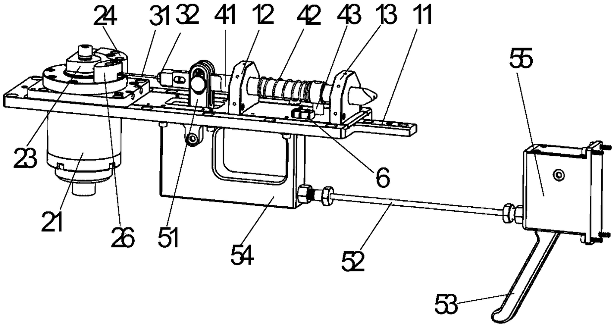
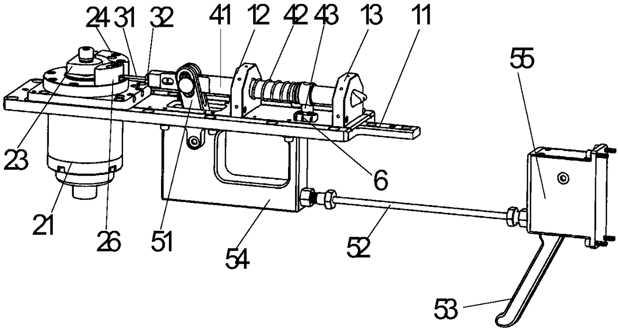
[0039] Such as figure 1 with 2 As shown, a marching fixer provided by Embodiment 1 of the present invention includes a base assembly 1 , a motor drive module 2 , a wire rope assembly 3 , a fixing pin assembly 4 , a manual unlock assembly 5 and a travel switch 6 .

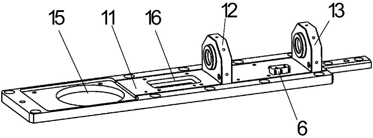
[0040] Such as image 3 As shown, the base assembly 1 includes a base plate 11, a front bearing seat 12 and a rear bearing seat 13, the front bearing seat 12 and the rear bearing seat 13 are fixedly arranged on the upper surface of the end portion of the base plate 11 from the inside to the outside, and the other side of the base plate 11 The upper surface of one end is sequentially provided with a manual unlocking component mounting hole 16 and an automatic unlocking component mounting hole 15 from the inside to the outside. In addition, a travel switch 6 is also arranged between the front bearing seat 12 and the rear bearing seat 13 of the base plate 11 .

[0041] Such as Figure 4 As shown, the fixed pin asse...

Embodiment 2

[0047] A marching fixer provided by Embodiment 2 of the present invention is similar to the structure of Embodiment 1 of the present invention, the difference is that, as Figure 10 As shown, in the inner holes of the front bearing seat 12 and the rear bearing seat 13 of the base assembly 1, the front guide tube 17 and the rear guide tube 18 are sleeved respectively to further support and accurately guide the fixed pin 41; in addition ,Such as Figure 11 As shown, in the motor drive module, a reduction mechanism 222 is also provided between the torque motor 21 and the hard block 23. Specifically, the reduction mechanism 222 is a pair of gears, and the torque motor 21 drives the hard block 23 to rotate through the pair of gears 222. , to achieve further precise control and stable operation; Figure 12 As shown, the outer ends of the release block 24 and the return block 26 are respectively provided with a release buffer pad 25 and a return buffer pad 27. When the unlocking is ...


PUM


Abstract

The invention discloses a marching fixture comprising an automatic unlocking assembly, a manual unlockingassembly, a dowel pin assembly, and a travel switch. The automatic unlocking assembly and the manual unlocking assembly are connected to the dowel pin assembly, respectively. A trigger block is arranged on the dowel pin assembly, which serves to trigger the travel switch to control the state of the marching fixture. The marching fixture of the invention allows control on the operating state thereof in such a manner of combined automatic unlocking and manual unlocking such that the reliability thereof can be effectively improved and the application range thereof can be extended; the marching fixture is good in temperature adaptability, especially capable of operating normally in low temperature environments, and is high in control accuracy, simple in integrated structure, reasonable in design, low in failure rate, simple and convenient in maintenance, and extensive in application prospect.

Description

technical field [0001] The invention relates to the field of mechanical transmission, more specifically, to a marching fixer. Background technique [0002] As an important auxiliary mechanism of launching devices such as rockets, the marching fixer can firmly fix the pitching and turning parts of the launching device during the marching process, and prevent the components of the launching device from being damaged due to the vibration and shock of the marching. The marching fixer can be divided into three modes: automatic, semi-automatic and manual according to its operation mode. Restrictions need to be lifted when aiming and shooting. In order to improve the rapid response capability of rockets and other weapons and equipment, when the marching fixer switches between marching and combat states, its operation should be mechanized or automated to ensure rapid movement. In the locked state, due to the inertial force and impact force of the pitching and turning part of the la...

Claims


Application Information

Patent Timeline
Patent Type & Authority Patents(China)
IPC IPC(8): F41A23/00
CPCF41A23/005
Inventor 何汉辉吴学忠肖定邦袁超席翔卢坤罗昊东
Owner NAT UNIV OF DEFENSE TECH
Why Eureka
Try Eureka