Joint location method applicable to improvement of micro-earthquake location reliability

A joint positioning and microseismic technology, applied in the fields of seismology, seismic signal processing, geophysical measurement, etc., can solve the problems of decreased positioning reliability, slow calculation efficiency, unable to meet the real-time monitoring of construction sites, etc., to ensure the calculation efficiency, The effect of solving the positioning abnormality and improving the positioning reliability

Active Publication Date: 2017-05-31
JILIN UNIV
View PDF7 Cites 12 Cited by
  • Summary
  • Abstract
  • Description
  • Claims
  • Application Information

AI Technical Summary

Problems solved by technology

However, for surface monitoring and downhole monitoring of shallow fracturing, the frequency of received microseismic signals is relatively high, generally in the range of 100Hz to 200Hz or even higher. The envelop is small, when using the method of successive grid subdivision, the first subdivision size is too large so that the grid

Method used


Image

  • Joint location method applicable to improvement of micro-earthquake location reliability
  • Joint location method applicable to improvement of micro-earthquake location reliability
  • Joint location method applicable to improvement of micro-earthquake location reliability

Examples


Embodiment 1

[0060] Embodiment 1: Microseismic events are located using the method of successive subdivision of 3D grids in the prior art

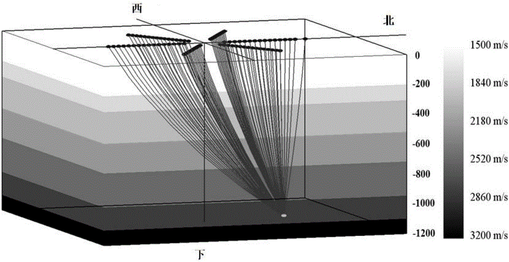
[0061] Firstly, the simulated microseismic event is positioned and processed by the grid subdivision algorithm successively, and a 7-layer stratigraphic model is established. The seismic wave is simulated by the seismic wavelet of 120 Hz. 16 geophones (96 channels) are arranged along the line, and the location where the microseismic event occurs is set as (-225, -147, -1062).

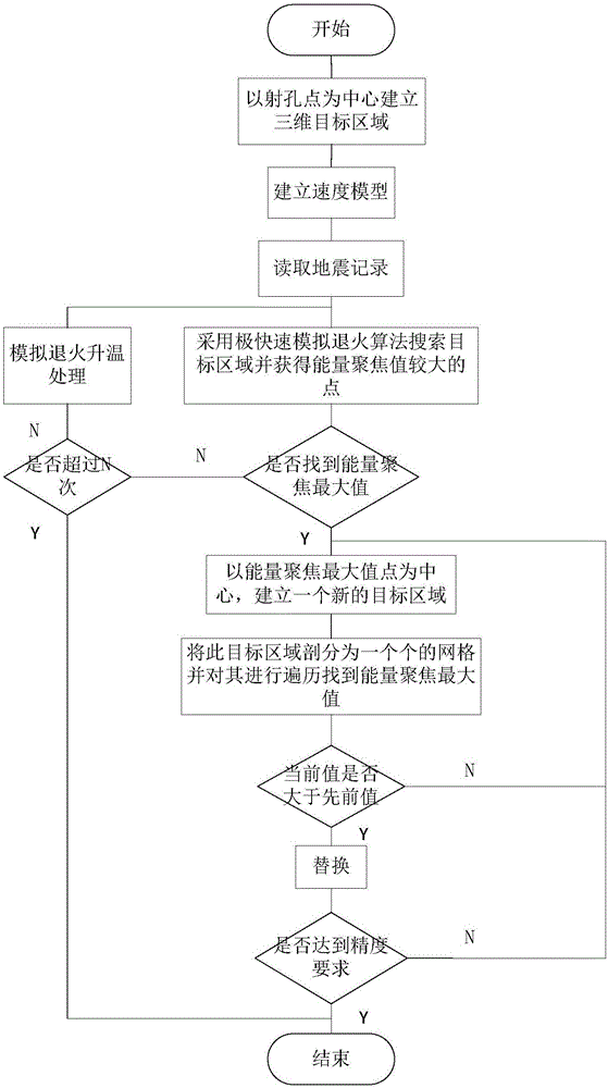
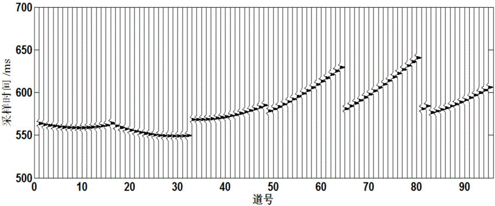
[0062] A. Define a three-dimensional target area near the perforation, and set the position of the target area as X∈[-300,300], Y∈[-300,300], Z∈[-1200,-800], that is, microseismic events may occur in this area event. And select a reference track M in the selected target area, which is required to have a relatively clear first-arrival event and a high signal-to-noise ratio.

[0063] B. Select the size of the first grid division as 40m, divide the selected target area into sever...

Embodiment 2

[0070] The present invention is used to locate the simulated source (i.e. the position where the microseismic event occurs). For convenience of comparison, its simulated model is the same as that of Embodiment 1, and a 7-layer stratum model is set up. The seismic wave adopts the seismic wavelet of 120 Hz to simulate. Six survey lines are arranged in a star shape, and 16 geophones (96 channels) are arranged on each survey line, and the location where the microseismic event occurs is set as (-225, -147, -1062).

[0071] A. Define a three-dimensional target area near the perforation, and set the position of the target area as X∈[-300,300], Y∈[-300,300], Z∈[-1200,-800], that is, microseismic events may occur in this area event. And select a target area as the reference trace M, which requires a relatively clear first-arrival event and a high signal-to-noise ratio.

[0072] B. Establish velocity model and read seismic records;

[0073] C. Under the speed model, first use the extr...


PUM


Abstract

The invention relates to a location method applicable to improvement of micro-earthquake location reliability. The method is characterized in that in view of shortcomings of a successive mesh generation micro-earthquake algorithm, in combination with a very fast simulated annealing algorithm, a micro-earthquake location algorithm is developed, which is based on joint very fast simulated annealing and successive mesh generation. According to the method, the very fast simulated annealing algorithm is employed to search for a highly energy-focused circular region in a three-dimensional target area, and then the successive mesh generation method is employed to search for a maximum energy-focused point in the area; thus, the problem of wrong location of the successive mesh generation method due to oversize primary mesh generation during location of a high-frequency seismic wave is effectively solved, and the location reliability is improved while the calculation efficiency is ensured.

Description

technical field [0001] The invention belongs to the technical field of oil field fracturing microseismic positioning, and relates to a joint positioning method suitable for improving the reliability of microseismic positioning. Background technique [0002] Microseismic monitoring is a fast and effective method to describe the development of hydraulic fracturing fractures. Reservoir stimulation personnel need to evaluate the hydraulic fracturing effect and adjust the fracturing construction parameters and construction plan in real time, which requires microseismic monitoring. Data for rapid processing and precise location of microseismic events. The original positioning method mainly comes from the single earthquake event positioning method proposed by Geiger. This method assumes the location of the source and the time of the earthquake, and then calculates the calculated arrival time from the source to each receiver point, and uses the calculated arrival time of all receive...

Claims


Application Information

Patent Timeline
IPC IPC(8): G01V1/28
CPCG01V1/288G01V2210/14
Inventor 陈祖斌王纪程江海宇吕昊
Owner JILIN UNIV
Why Eureka
Try Eureka