
Method for correcting ortho-image mosaic edge matching

An orthophoto and image technology, which is applied in the field of edge correction of orthoimage mosaic, can solve the problems of image blur, image dislocation, and reduce the accuracy of spliced ​​images, so as to improve the edge accuracy and ensure the geometric accuracy.

Active Publication Date: 2017-05-31
BEIJING AEROSPACE TITAN TECH CO LTD
View PDF5 Cites 1 Cited by
  • Summary
  • Abstract
  • Description
  • Claims
  • Application Information

AI Technical Summary

Problems solved by technology

If no processing is done on the deviation of the geometric position of the image, the spliced ​​image will have obvious misalignment, ghosting, and image blur, thereby reducing the accuracy of the spliced ​​image

Method used


Image

  • Method for correcting ortho-image mosaic edge matching
  • Method for correcting ortho-image mosaic edge matching
  • Method for correcting ortho-image mosaic edge matching

Examples


Embodiment 1

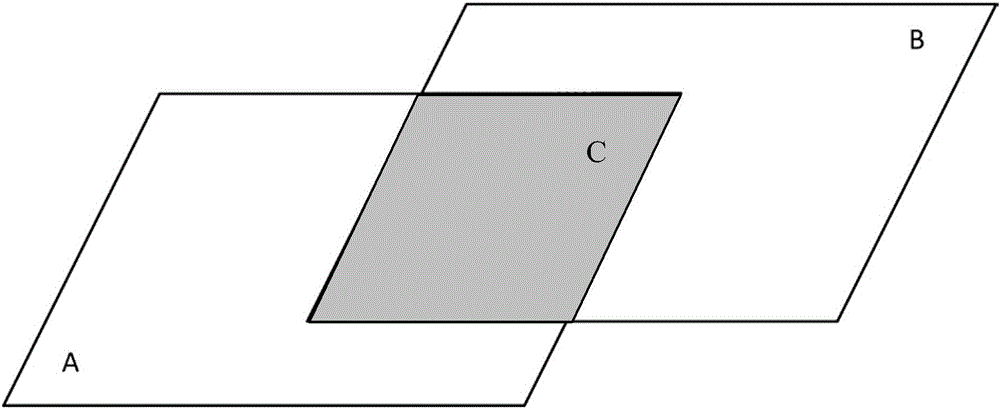
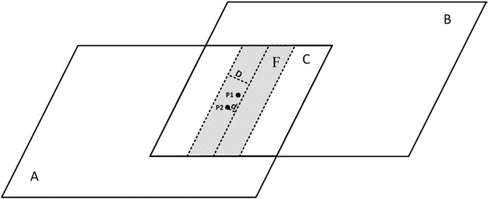
[0082] Embodiment one, such as image 3 As shown, when two adjacent orthophotos A and B are rectified, the point P with the same name 1 and P 2 When both are within the buffer range, such as Figure 2-2 P shown 1 and P 2 Position, for any point within the buffer zone on the orthophoto on the left side of the boundary line, the geographic coordinates P 1 (x 1 ,y 1 ), corresponding to the geographic coordinates P of the point with the same name on the right orthophoto 2 (x 2 ,y 2 ), (Δx, Δy) are two points P with the same name 1 and P 2 The geographic coordinate difference of Figure 2-2 If the left image A is used as the reference to correct the right image B, then the point P with the same name to be corrected must be 2 The geographic coordinate correction values ​​are:

[0083]

[0084] where Δx' represents the pair P in the image 1 The correction value of the geographical coordinates in the x-axis direction of the point, Δy' represents the correction value o...

Embodiment 2

[0085] Embodiment 2, when two adjacent images have the same name point P 1 Within the buffer range, P 2 When on the border line, d is 0 at this time, such as Figure 5 The position of the point with the same name shown is:

[0086]

Embodiment 3

[0087] Embodiment three, for such as Figure 6 P 1 and P 2 location as an example, when P 1 point lies within the buffer range and P 2 When the point is on the boundary of the buffer zone, d=D at this time, there are:

[0088]

[0089] When P 2 When the points are located on the boundary line and the boundary line of the buffer zone, the calculated P 2 In terms of point geographic coordinate correction value, when using the orthophoto mosaic edge correction method in the present invention, the closer the point to be corrected with the same name is to the edge line, the larger the geographic coordinate correction value is, and vice versa.

[0090] S5. Geographically correct the geographic coordinates of the points with the same name in the image to be corrected within the buffer zone

[0091] When two points with the same name are located in the buffer zone, such as Figure 2-2 P shown in 1 and P 2 The position of the same name point to be corrected is calculated ac...


PUM


Abstract

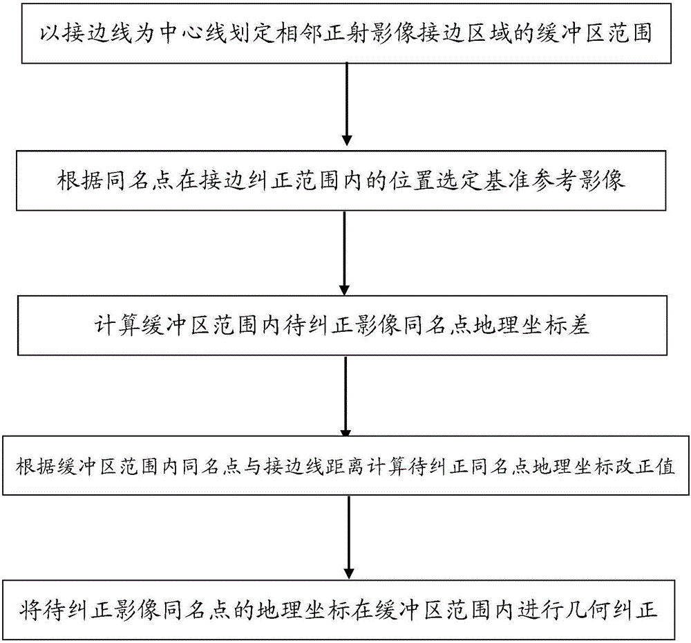
The invention provides a method for correcting ortho-image mosaic edge matching. The method comprises the following steps of: determining positions of same-name points in an edge matching are of adjacent ortho-images; demarcating an edge matching correction range in the edge matching area; and selecting a standard reference image according to the positions of the same-name points in the edge matching correction range, and correcting to-be-corrected images of other non-standard reference images onto the standard reference image. According to the method, the aim of correcting ortho-image mosaic edge matching is achieved in a range with a certain distance to an edge matching line, and the image correction is controlled in a certain range when the edge matching correction precision is ensured, so that the edge matching precision of adjacent images is effectively improved, and the integral geometric precision of large-area mosaic images is ensured at the same time.

Description

technical field [0001] The invention relates to the technical field of large-area orthophoto mosaic deviation correction, in particular to a method for correcting edges of orthophoto mosaic. Background technique [0002] There are two main types of image stitching algorithms: one is the stitching algorithm based on region correlation, and the other is the stitching algorithm based on feature correlation. The former mainly depends on the gray value of the image, and the image to be stitched and the target image are judged by the size or ratio of the gray value of the two in the same area, so as to realize the stitching of the image. The latter mainly uses the image features derived from the image pixels as the standard to search and match the corresponding feature areas of the overlapping parts of the images. The above methods are all based on the seam selection between adjacent images, which only eliminate artificial false edges, but do not really solve the geometric qualit...

Claims


Application Information

Patent Timeline
Patent Type & Authority Applications(China)
IPC IPC(8): G06T3/40G06T5/00
CPCG06T3/4038G06T2207/30181G06T5/80
Inventor 李传广王红燕苏晓玉钱晓明
Owner BEIJING AEROSPACE TITAN TECH CO LTD
Learn More