Two dimension situation map forming method and electronic equipment

A two-dimensional situation and static image technology, applied in the electronic field, can solve the problems of interface redundancy, increased development difficulty and workload of three-dimensional display, and narrow display range of three-dimensional display, so as to achieve simplified technical effect, small software development workload and effect of difficulty

Inactive Publication Date: 2017-05-31
SICHUAN JIUZHOU ELECTRIC GROUP
View PDF4 Cites 5 Cited by
  • Summary
  • Abstract
  • Description
  • Claims
  • Application Information

AI Technical Summary

Problems solved by technology

[0006] However, when the first method is used for situation display, too many text descriptions will cause redundant interface, and the rigid static icons cannot give users a more friendly experience; when the second method is used, the three-dimensional display will inevitably increase the difficulty of development and workload. At the same time, due to the narrow display range of the three-dimensional display, it is basically impossible to display the operation of all monitoring entities at the same time.

Method used


Image

  • Two dimension situation map forming method and electronic equipment
  • Two dimension situation map forming method and electronic equipment
  • Two dimension situation map forming method and electronic equipment

Examples


Embodiment 1

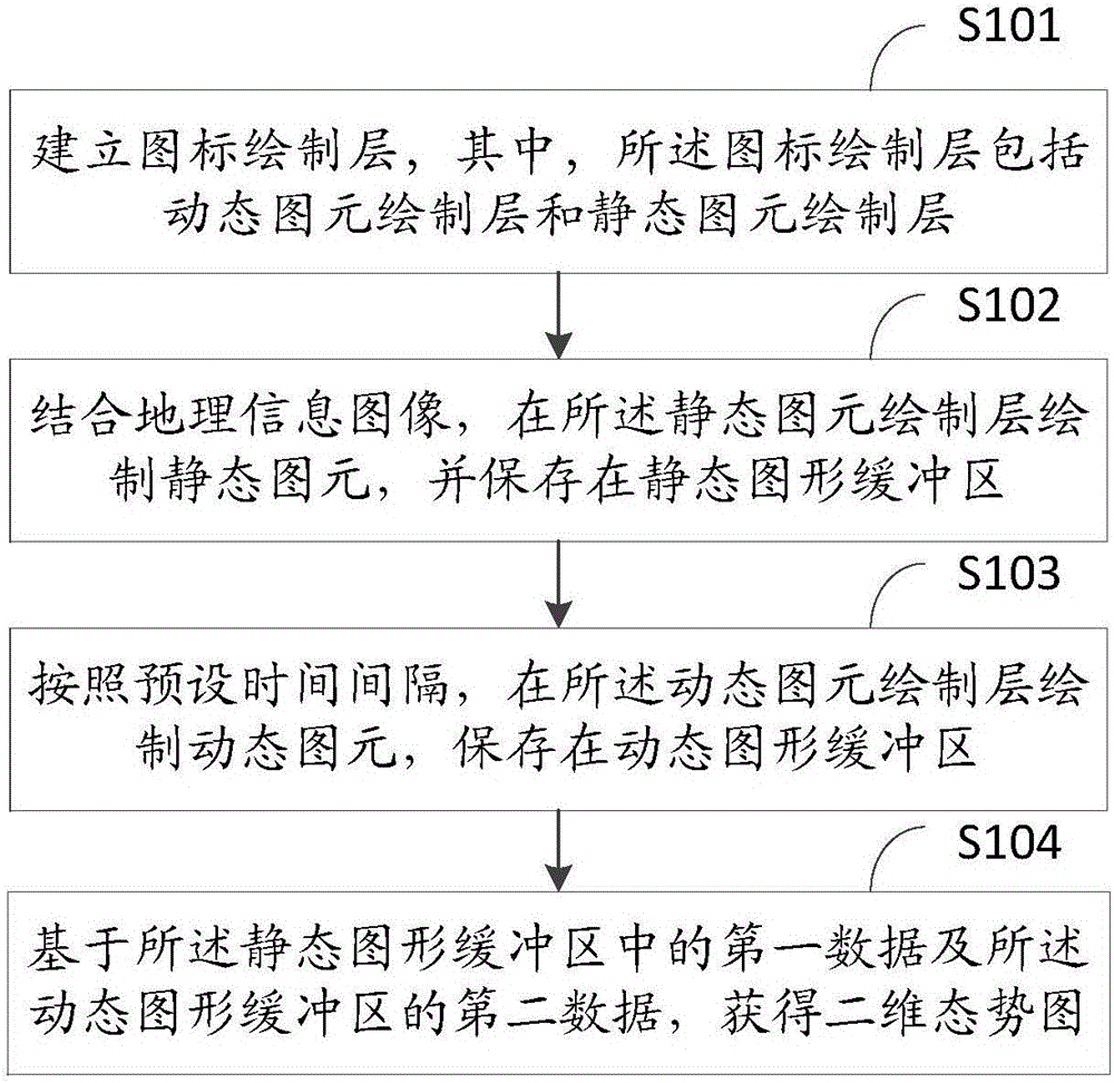
[0103] Please refer to figure 1 , which is a flowchart of a method for generating a two-dimensional situation map provided in Embodiment 1 of the present application, the method includes:

[0104] S101: Establish an icon drawing layer, wherein the icon drawing layer includes a dynamic graphic element drawing layer and a static graphic element drawing layer;

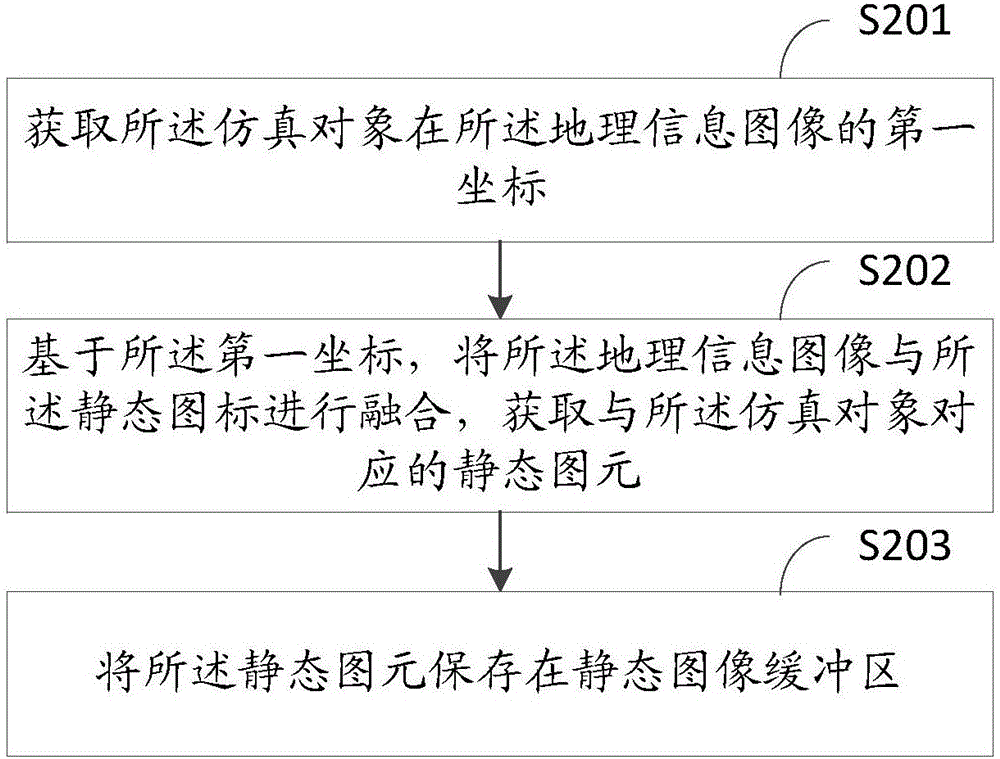
[0105] S102: Combining with geographic information images, draw static primitives in the static primitive drawing layer, and save them in a static graphics buffer;

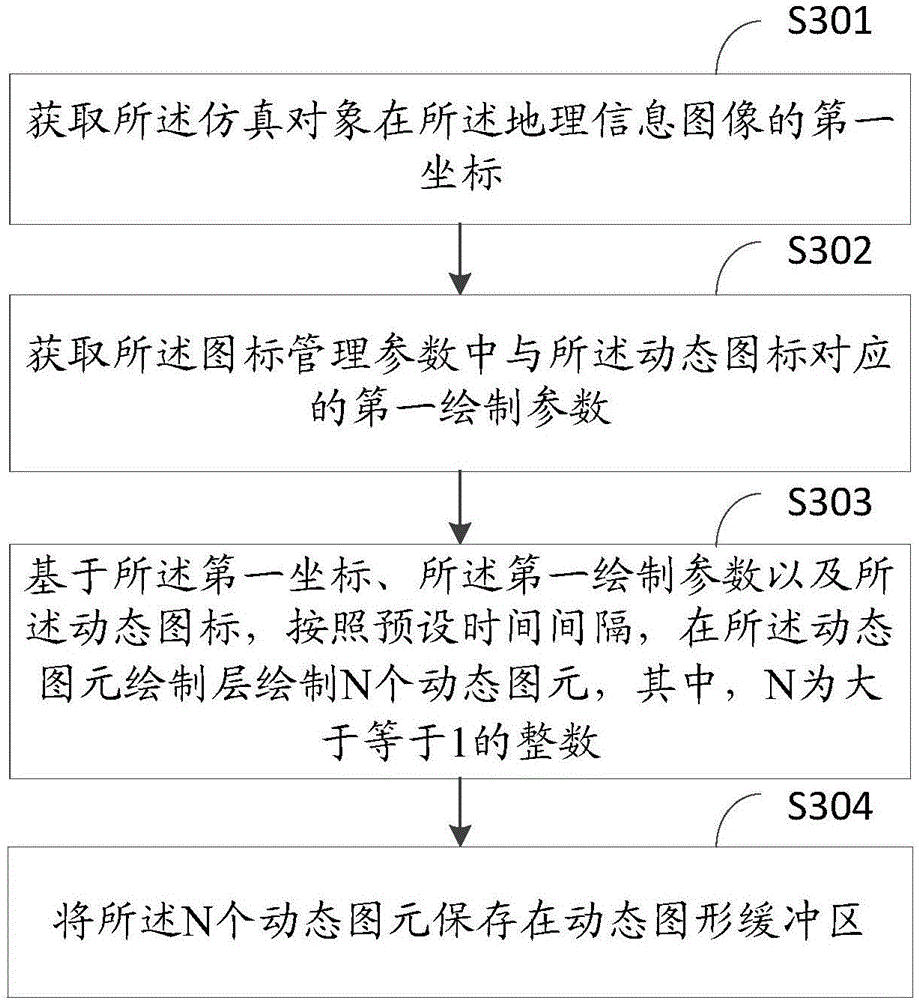
[0106] S103: Draw dynamic primitives in the dynamic primitive drawing layer according to a preset time interval, and save them in a dynamic graphics buffer;

[0107] S104: Obtain a two-dimensional situation map based on the first data in the static graphics buffer and the second data in the dynamic graphics buffer.

[0108] In the specific implementation process, the method for generating the two-dimensional situation diagram can be applied in multiple fiel...

Embodiment 2

[0156] Based on the same inventive concept as Embodiment 1 of this application, please refer to Figure 6 , which is a structural block diagram of an electronic device provided in Embodiment 2 of the present application, and the electronic device includes:

[0157] A first determining unit 101, configured to determine a simulation object;

[0158] The second obtaining unit 102 is configured to obtain an entity icon corresponding to the simulation object, wherein the entity icon includes a dynamic icon and a static icon, and the dynamic icon is a dynamic attribute that changes with time in the simulation object A corresponding icon, the static icon is an icon corresponding to a static attribute that does not change over time in the simulation object;

[0159] The third obtaining unit 103 is configured to obtain an icon management parameter corresponding to the entity icon, wherein the icon management parameter is a parameter used to manage drawing parameters of the dynamic ico...


PUM


Abstract

The invention discloses a two dimension situation map forming method and electronic equipment; the method comprises the following steps: building an icon drafting layer, wherein the icon drafting layer comprises a dynamic graphics primitive drafting layer and a static graphics primitive drafting layer; combining a geography information image, drafting static graphics primitives in the static graphics primitive drafting layer, and storing same in a static graphics buffer zone; drafting dynamic graphics primitives in the dynamic graphics primitive drafting layer according to a preset time interval, and storing same in a dynamic graphics buffer zone; obtaining a two dimension situation map according to the first data in the static graphics buffer zone and the second data in the dynamic graphics buffer zone. A conventional method cannot directly display a simulation entity state in real time; the two dimension situation map forming method can solve said problems, can directly display the simulation entity important state information as much as possible in real time in a limited display interface under small software developing workload and difficulty, thus simplifying the simulation entity real time information display modes.

Description

technical field [0001] The invention relates to the field of electronic technology, in particular to a method for generating a two-dimensional situation graph and electronic equipment. Background technique [0002] In the process of visual simulation or military deduction, two-dimensional situation diagrams are often used to display the real-time status of the monitored entities or the forces of both parties in the deduction. icon, and assist in matching related text information and other relevant descriptions to describe the real-time status of the simulation entity. With the continuous improvement of computer drawing capabilities and the diversification of information display, a dynamic icon is designed to display real-time key information of the simulation entity, such as controlling the propeller rotation speed of the helicopter icon to reflect the motion state of the helicopter, and receiving antennas on the radar icon It is an urgent problem to be solved in the situat...

Claims


Application Information

Patent Timeline
Patent Type & Authority Applications(China)
IPC IPC(8): G06T11/40
CPCG06T11/40
Inventor 李硕任丽萍陈乾友龚红伟李维谦
Owner SICHUAN JIUZHOU ELECTRIC GROUP
Why Eureka
Try Eureka