
Array substrate and control method thereof

A technology of array substrates and control lines, applied in instruments, semiconductor devices, electrical components, etc., can solve the problem of a single way of changing the brightness, and achieve the effect of enriching the ways of changing the brightness

Inactive Publication Date: 2019-09-13
BOE TECH GRP CO LTD +1
View PDF5 Cites 0 Cited by
  • Summary
  • Abstract
  • Description
  • Claims
  • Application Information

AI Technical Summary

Problems solved by technology

[0005] In order to solve the problem of a single way to change brightness, an embodiment of the present invention provides an array substrate and a control method thereof

Method used


Image

  • Array substrate and control method thereof
  • Array substrate and control method thereof
  • Array substrate and control method thereof

Examples


Embodiment Construction

[0052] In order to make the purpose, technical solution and advantages of the present application clearer, the implementation manners of the present application will be further described in detail below in conjunction with the accompanying drawings.

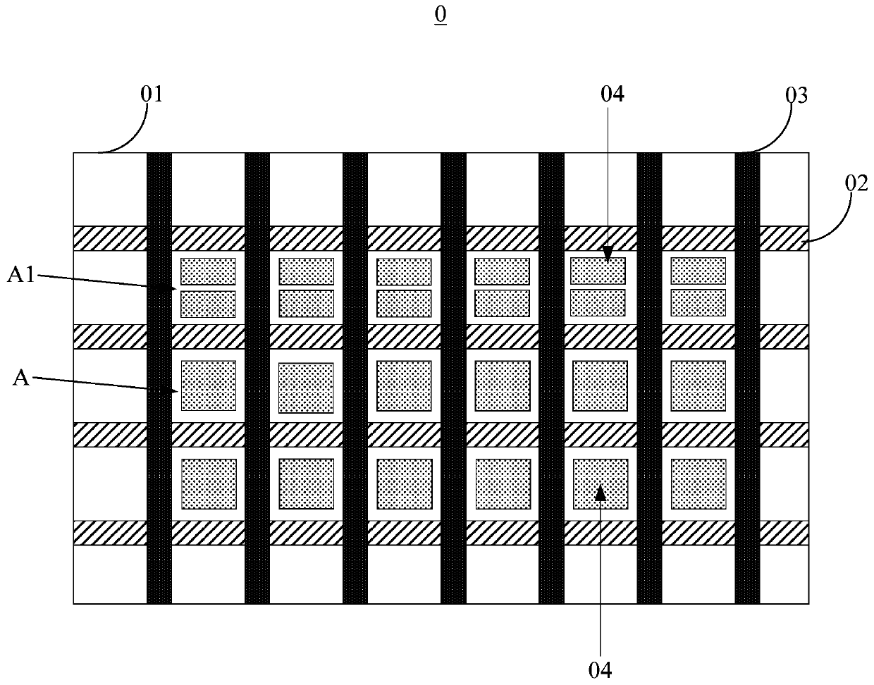
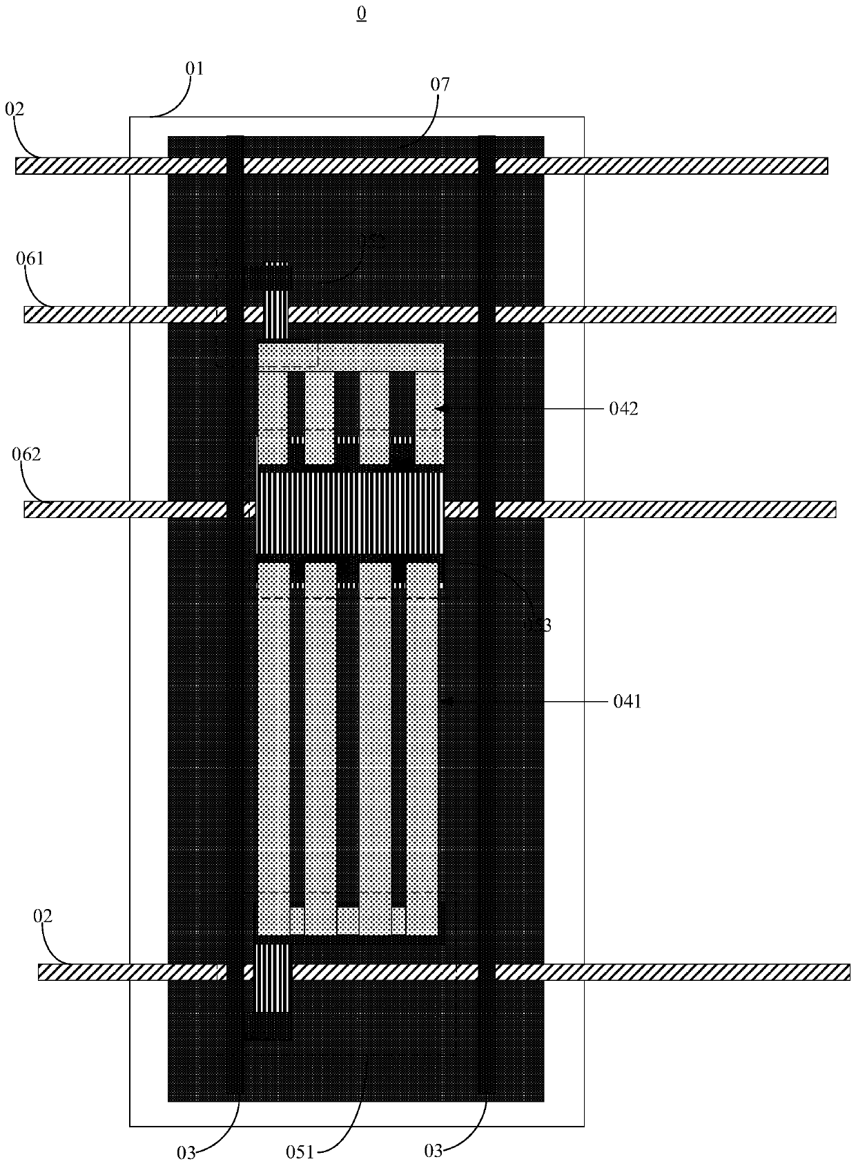
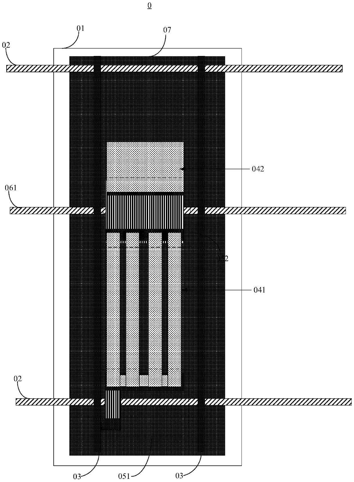
[0053] figure 1 A schematic structural diagram of an array substrate 0 provided for an embodiment of the present invention, as shown in figure 1 As shown, the array substrate 0 may include: a base substrate 01; a plurality of gate lines 02, a plurality of data lines 03, a plurality of pixel electrodes 04 and a plurality of TFTs ( figure 1 Not shown in), each pixel electrode 04 is controlled by a TFT;

[0054] Wherein, a plurality of gate lines 02 and a plurality of data lines 03 surround a plurality of pixel regions A arranged in an array, there is at least one target pixel region A1 in the plurality of pixel regions A, and at least two pixels are arranged in the target pixel region A1 Electrode 04 ( figure 1 In the example, t...


PUM


Abstract

The application discloses an array substrate and a control method thereof and belongs to the technical field of display. The array substrate comprises a substrate plate provided with a plurality of grid lines, a plurality of data lines, a plurality pixel electrodes and a plurality of thin film transistors (TFT). Each of the pixel electrodes is controlled by one TFT. The grid lines and the data lines surround to form multiple pixel regions in array arrangement; at least one target pixel region exists in the multiple pixel regions; at least two pixel electrodes are arranged in the target pixel region. By application of the array substrate and the control method thereof, the problem of single way of changing brightness is solved, and brightness changing way is enriched. The array substrate is applied to display panels.

Description

technical field [0001] The present application relates to the field of display technology, in particular to an array substrate and a control method thereof. Background technique [0002] With the development of display technology, display panels have been widely used. The display panel includes an array substrate and a color filter substrate oppositely arranged, and a liquid crystal located between the array substrate and the color filter substrate. [0003] The array substrate includes a first base substrate, on which a plurality of gate lines and data lines intersecting are arranged, and the gate lines and data lines intersect to form a plurality of pixel areas, and each pixel area is provided with a Thin Film Transistor (English: Thin Film Transistor; TFT for short) structure and a pixel electrode, the gate of the TFT is connected to the gate line, the source of the TFT is connected to the data line, and the drain of the TFT is connected to the pixel electrode. The colo...

Claims


Application Information

Patent Timeline
Patent Type & Authority Patents(China)
IPC IPC(8): H01L27/12G02F1/1362
Inventor 李艳高博时凌云孙伟
Owner BOE TECH GRP CO LTD
Learn More