Antenna radiation pattern reconstructible method, antenna device and wireless communication equipment

A technology of wireless communication equipment and antenna pattern, which is applied to antennas, antenna combinations with different interactions, electrical components, etc., can solve the problems of great design difficulty, antenna deterioration, and difficulty in achieving design effects, and improve the actual Experience, respond to harsh requirements, and ensure the effect of normal communication quality

Active Publication Date: 2017-05-31
QINGDAO HISENSE MOBILE COMM TECH CO LTD
View PDF8 Cites 12 Cited by
  • Summary
  • Abstract
  • Description
  • Claims
  • Application Information

AI Technical Summary

Problems solved by technology

However, as the mobile communication environment becomes more and more complex, and the environment reserved for the antenna in the mobile terminal evaluation is deteriorating, this design method of imp

Method used


Image

  • Antenna radiation pattern reconstructible method, antenna device and wireless communication equipment
  • Antenna radiation pattern reconstructible method, antenna device and wireless communication equipment
  • Antenna radiation pattern reconstructible method, antenna device and wireless communication equipment

Examples


Embodiment 1

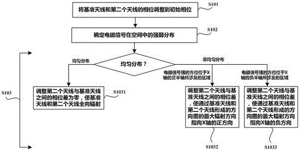
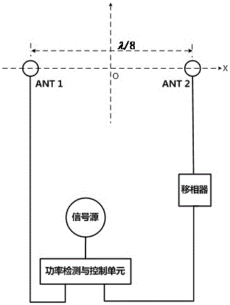
[0023] Embodiment 1. In this embodiment, two antennas are set in the wireless communication device, such as figure 2 As shown, one of the antennas ANT1 is selected as the reference antenna, and the distance between the second antenna ANT2 and the reference antenna ANT1 is set to λ / 8. In this embodiment, the λ represents the wavelength of the electromagnetic signal to be received by the reference antenna ANT1 and the second antenna ANT2. For mobile phones, this is the wavelength of the communication signal (radio signal) transmitted through the base station antenna.

[0024] In order to more clearly describe the relative positional relationship between the reference antenna ANT1 and the second antenna ANT2 , this embodiment is explained by establishing a first plane Cartesian coordinate system. Both the reference antenna ANT1 and the second antenna ANT2 are arranged on the axis of the X-axis of the first plane Cartesian coordinate system, and the middle point of the reference...

Embodiment 2

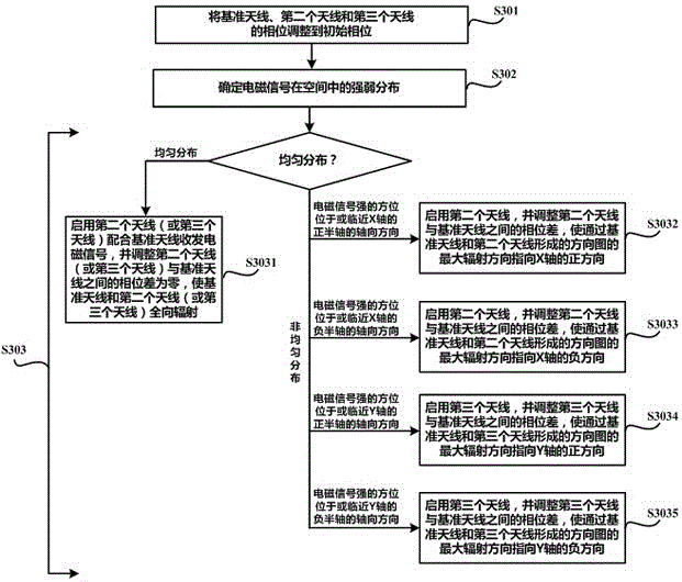
[0042] Embodiment 2. In this embodiment, three antennas are set in the wireless communication device, such as Figure 4 As shown, one of the antennas ANT1 is selected as the reference antenna, the distance between the second antenna ANT2 and the reference antenna ANT1 is set to λ / 8, and the distance between the third antenna ANT3 and the reference antenna ANT1 is also set to λ / 8. In this embodiment, the λ represents the wavelength of the electromagnetic signal to be received by the reference antenna ANT1 , the second antenna ANT2 and the third antenna ANT3 . For mobile phones, this is the wavelength of the communication signal (radio signal) transmitted through the base station antenna.

[0043] In order to more clearly describe the relative positional relationship between the second antenna ANT2, the third antenna ANT3 and the reference antenna ANT1, this embodiment is carried out by establishing a first plane rectangular coordinate system and a second plane rectangular coord...


PUM


Abstract

The invention discloses an antenna radiation pattern reconstructible method, an antenna device and wireless communication equipment. The method comprises the steps of selecting one antenna as a reference antenna, and arranging a second antenna at a position which is separated from the reference antenna by a distance of lambda/8; determining strength arrangement of an electromagnetic signal in a space; and adjusting a phase difference between the second antenna and the reference antenna so that a maximal radiation direction of an antenna system which is formed by the second antenna and the reference antenna is aligned to or next to a direction with highest electromagnetic strength in the space. According to the antenna radiation pattern reconstructible method, the antenna device and the wireless communication equipment, through arranging a plurality of antennae in the wireless communication equipment, the phase difference among the plurality of antennae is automatically adjusted according to change of a communication environment in which the wireless communication equipment exists, thereby realizing intelligent switching of the radiation pattern of the antenna device from omnidirectional to directional; through adjusting the maximal radiation direction of the antenna radiation pattern for being aligned to or next to the direction with best communication signal in the communication environment, optimal signal exchange between sets of equipment can be realized, and furthermore communication performance of the wireless communication equipment is remarkably improved.

Description

technical field [0001] The invention belongs to the technical field of antenna devices, and in particular relates to a method and an antenna device capable of realizing reconfiguration of an antenna pattern. Background technique [0002] With the development of technology and the progress of society, mobile communication has been closely linked with everyone's life. At the same time, realizing high-quality communication at any time and any place has always been a problem that mobile communication researchers must face. Of course, this is also the communication effect pursued by mobile terminal users. [0003] However, the reality is not completely consistent with the theory or imagination. The contradiction between the complex mobile communication environment and the existing mobile terminal design makes the communication quality of the mobile terminal in some places sometimes poor or even unable to achieve communication. The fundamental reason is that when designing the an...

Claims


Application Information

Patent Timeline
IPC IPC(8): H01Q3/30H01Q21/29
CPCH01Q3/30H01Q21/29
Inventor 吴凯胡育根郭湘荣
Owner QINGDAO HISENSE MOBILE COMM TECH CO LTD
Why Eureka
Try Eureka