Novel double-layer wave winding method capable of saving wiring space of outlet terminal

A wiring space and wave winding technology, which is applied in the field of new double-layer wave winding, can solve the problems of tight wiring space at the outlet end, the inability to use the △ connection method, and tight welding space, etc., so as to alleviate the tight wiring space and facilitate parallel head welding The effect of the operation

Active Publication Date: 2017-05-31
江西江特电机有限公司 +1
View PDF4 Cites 23 Cited by
  • Summary
  • Abstract
  • Description
  • Claims
  • Application Information

AI Technical Summary

Problems solved by technology

The disadvantages are: ①. The wiring space at the outlet end is tight, from figure 1 and figure 2 It can be seen that there are (number of rotor slots + 6) outlets evenly distributed at the outlet end, and the space for parallel welding of the ends is tight.
The disadvantages are: ①. There is one less conductor in each phase in the magnetic field, and the induced potential is correspondingly reduced; ②. Due to the noise of twice the slip frequency and the non-symmetrical distribution of the layer change line along the circumference, which affects the mechanical balance, it is not suitable It is used on motors with multiple poles of 6; ③, the outgoing line cannot use △ connection

Method used


Image

  • Novel double-layer wave winding method capable of saving wiring space of outlet terminal
  • Novel double-layer wave winding method capable of saving wiring space of outlet terminal
  • Novel double-layer wave winding method capable of saving wiring space of outlet terminal

Examples


Embodiment Construction

[0018] The following will clearly and completely describe the technical solutions in the embodiments of the present invention with reference to the accompanying drawings in the embodiments of the present invention. Obviously, the described embodiments are only part of the embodiments of the present invention, not all of them. Based on the embodiments of the present invention, all other embodiments obtained by persons of ordinary skill in the art without making creative efforts belong to the protection scope of the present invention. Additionally, the protection scope of the present invention should not be limited only to the following specific structures or components or specific parameters.

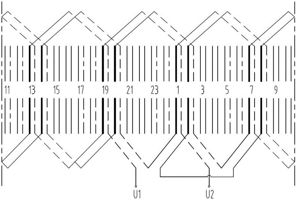
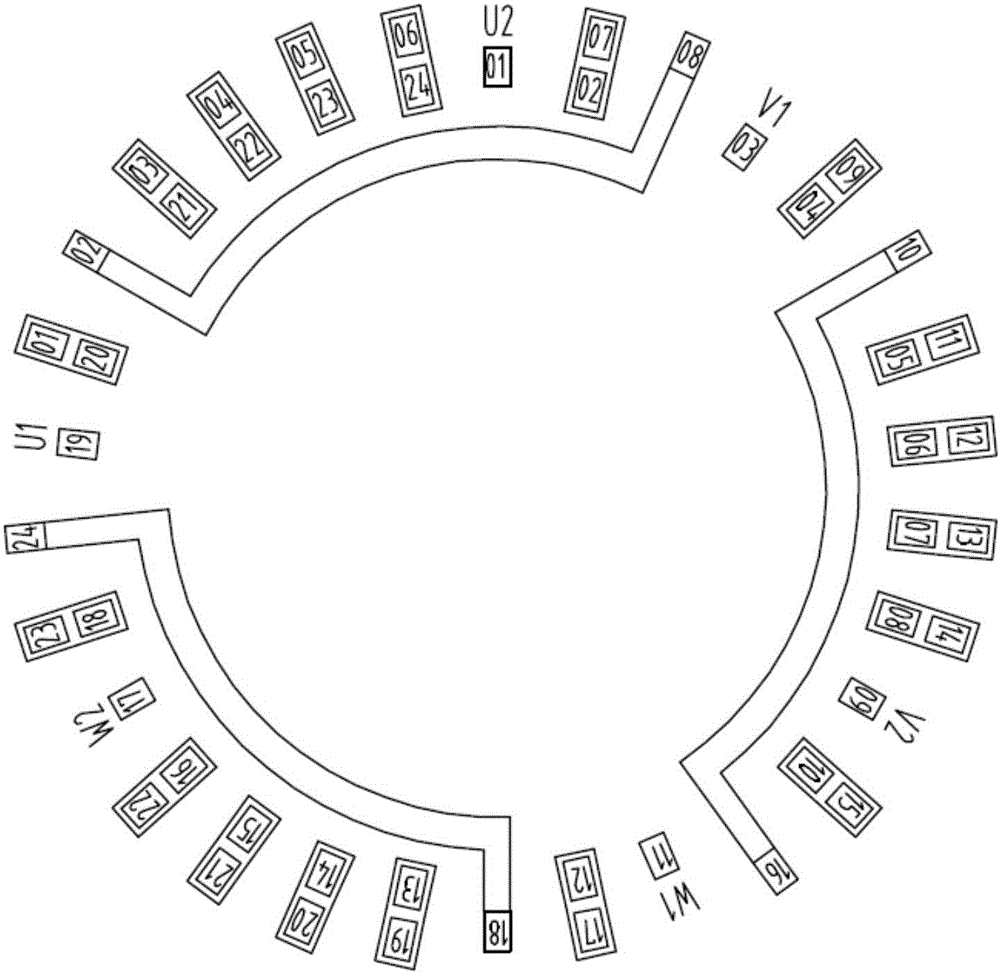
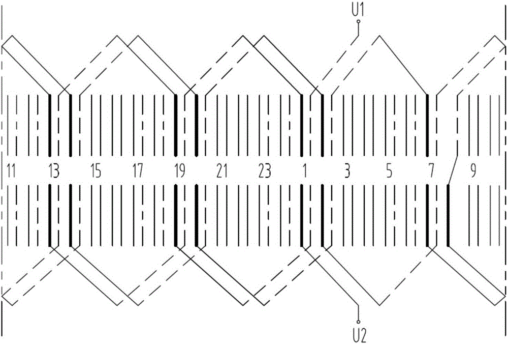
[0019] see figure 1 , the present invention works and implements in this way, a new double-layer wave winding method that can save the wiring space at the outlet end; taking the rotor with 4 poles and 24 slots, full pitch, and one-way connection as an example, it is characterized in tha...


PUM


Abstract

The invention discloses a novel double-layer wave winding method capable of saving wiring space of an outlet terminal. The novel double-layer wave winding method capable of saving the wiring space of the outlet terminal adopts multiple methods such as a full pitch one route connection method of a 4-pole 24-slot rotator, and the connection method includes: from the beginning of connection performed by using U1 as a leading wire, first connecting for 1-8 long pitches, then connecting for 3 whole pitches, next connecting for 2-7 short pitches, finally connecting for 3 whole pitches, completing connection of coils belonging to the same phase under U phase N pole, connecting coils under U phase S pole through steps as same as above steps, and finally connecting the coils of the two large groups in series according to the current direction in a slot, and then forming a phase of winding. The novel double-layer wave winding method capable of saving the wiring space of the outlet terminal has advantages of evenly distributing line outgoing heads of the same quantity as rotor slots at a line outgoing terminal by changing a connection mode of the double layer wave winding, alleviating the problem that wiring space is limited at the end of the line outgoing terminal to obtain the maximum distance between each two adjacent line outgoing heads and the maximum operation space of uniform head welding, facilitating uniform head welding operation to the utmost, placing head and tail connection lines of both the phases at one end, and connecting outgoing lines through a Y connecting method and a delta connection method.

Description

technical field [0001] The invention relates to a motor winding, in particular to a novel double-layer wave winding method which can save wiring space at outlet terminals. Background technique [0002] Double-layer wave winding connections are widely used in motor windings, especially rotor windings. There are two traditional connection methods for double-layer wave windings: one-end outlet and two-end outlet, such as Figure 1-4 As shown, taking the 4-pole, 24-slot, full-pitch, one-way, double-layer wave winding of the rotor as an example, the characteristics of the two traditional connection methods are analyzed. according to Figure 1-Figure 4 According to the demonstration, the characteristics of the traditional rotor wave winding, the characteristics of the two-end outlet and one-end outlet are compared as follows: [0003] The advantages of the traditional double-layer wave winding with one end of the double-layer wave winding connection are as follows: ①, it can...

Claims


Application Information

Patent Timeline
Patent Type & Authority Applications(China)
IPC IPC(8): H02K3/28
CPCH02K3/28
Inventor 王卫平何铎艾音东
Owner 江西江特电机有限公司
Why Eureka
Try Eureka