A swinging vibration energy harvesting device

A vibration energy collection, swinging technology, applied in the direction of electromechanical devices, electrical components, etc., can solve the problem of low collection efficiency, achieve the effect of improving utilization, eliminating positioning force, and improving energy collection efficiency

Active Publication Date: 2019-02-12
ZHEJIANG UNIV OF TECH
View PDF5 Cites 1 Cited by
  • Summary
  • Abstract
  • Description
  • Claims
  • Application Information

AI Technical Summary

Problems solved by technology

[0005] In order to overcome the shortcomings of the low collection efficiency of existing vibration energy harvesting devices, the present invention provides a swing type vibration energy harvesting device with high collection efficiency

Method used


Image

  • A swinging vibration energy harvesting device
  • A swinging vibration energy harvesting device
  • A swinging vibration energy harvesting device

Examples


Embodiment Construction

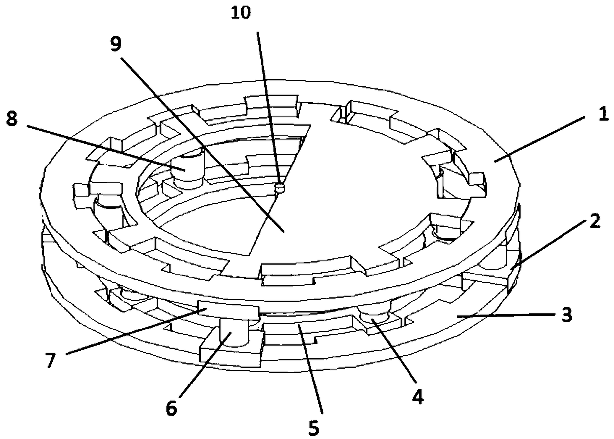
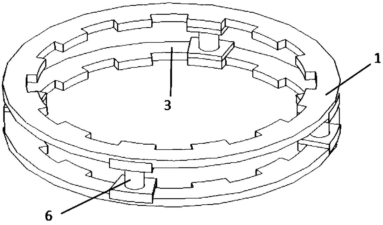
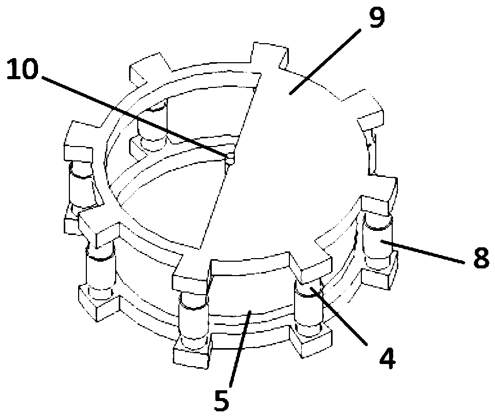
[0025] The present invention will be further described below in conjunction with the accompanying drawings.

[0026] refer to Figure 1 to Figure 6 , a swing type vibration energy harvesting device, comprising a casing 11, the energy harvesting device also includes a stator assembly and a rotor assembly located in the casing, the stator assembly includes a permanent magnet 6, and the permanent magnet 6 is placed in a vertical direction, The top is the N pole, and the bottom is the S pole; the N pole of the permanent magnet 6 is connected with the upper bracket 7 of the permanent magnet, and the S pole of the permanent magnet 6 is connected with the lower bracket 5 of the permanent magnet, and the upper bracket 7 of the permanent magnet is connected with the permanent magnet upper bracket 5. The outer upper yoke 1 is connected, the permanent magnet lower bracket 5 is connected with the outer lower yoke 3, and the permanent magnets 6 are arranged in a circumferential circle of t...


PUM


Abstract

The invention discloses an oscillating type vibrating energy collecting device. The oscillating type vibrating energy collecting device comprises a casing, a stator assembly and a rotor assembly, wherein permanent magnets are vertically arranged in the stator assembly; the permanent magnets are arranged on circumferences of an external upper magnet yoke and an external lower magnet yoke at equal circular arc in a spacing manner; coils are arranged on an iron core in the rotor assembly; 2n iron cores are arranged on the circumferences of a rotor upper magnet yoke and a rotor lower magnet yoke at equal circular arc in the spacing manner; a shaft is arranged between the rotor upper magnet yoke and the rotor lower magnet yoke; 2n magnetic teeth are arranged on outer rings of the rotor upper magnet yoke and the rotor lower magnet yoke at equal circular arc in the spacing manner; the clearance of the magnetic teeth is greater than twice the width of each magnetic tooth; 3n magnetic teeth are arranged on inner rings of the external upper magnet yoke and the external lower magnet yoke at equal circular arc in the spacing manner; the width of each magnetic tooth is equal to the clearance between the magnetic teeth; the rotor upper magnet yoke is positioned in the external upper magnet yoke and the magnetic teeth between the rotor upper magnet yoke and the external upper magnet yoke make contact; the rotor lower magnet yoke is positioned in the external lower magnet yoke and the magnetic teeth between the rotor lower magnet yoke and the external lower magnet yoke make contact; the magnetic tooth width of the rotor magnet yoke is smaller than the magnetic tooth clearance of the external magnet yoke. The oscillating type vibrating energy collecting device disclosed by the invention is higher in collecting efficiency.

Description

technical field [0001] The invention relates to an energy harvesting device, in particular to a swing type vibration energy harvesting device. Background technique [0002] The power supply problem of wireless sensor network or distributed small system is a difficult point in application. Vibration is a form of energy in nature. For example, the waves of the sea, the swing of branches in the wind, bumpy vehicles, etc. Vibration power generation is to convert the energy generated by various vibrations into electrical energy. It is a potential new power generation device that is pollution-free and does not consume natural resources. It is suitable for wireless sensor networks or distributed small system nodes. [0003] One way to achieve vibration power generation is through the phenomenon of electromagnetic induction. Conventional electromagnetic induction vibration power generation devices have different internal structures. The three-dimensional vibration generator with...

Claims


Application Information

Patent Timeline
Patent Type & Authority Patents(China)
IPC IPC(8): H02K35/02
CPCH02K35/02
Inventor 王满州张端
Owner ZHEJIANG UNIV OF TECH
Why Eureka
Try Eureka