LPMSM (linear permanent magnet synchronous motor) with low-thrust fluctuation

A permanent magnet synchronous motor and low-thrust technology, applied in the direction of electrical components, electromechanical devices, propulsion systems, etc., can solve problems such as fluctuations, and achieve the effects of eliminating end positioning force, reducing unbalance, and reducing electromagnetic force fluctuations

Active Publication Date: 2013-03-27
HARBIN INST OF TECH
View PDF4 Cites 5 Cited by
  • Summary
  • Abstract
  • Description
  • Claims
  • Application Information

AI Technical Summary

Problems solved by technology

[0007] In order to solve the fluctuation problem existing in the existing low-thrust linear motor, the present invention proposes a low-thrust fluctuation linear permanent magnet synchronous motor

Method used


Image

  • LPMSM (linear permanent magnet synchronous motor) with low-thrust fluctuation
  • LPMSM (linear permanent magnet synchronous motor) with low-thrust fluctuation
  • LPMSM (linear permanent magnet synchronous motor) with low-thrust fluctuation

Examples


specific Embodiment approach 1

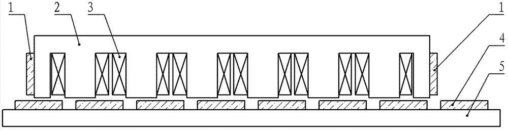
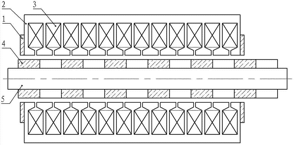
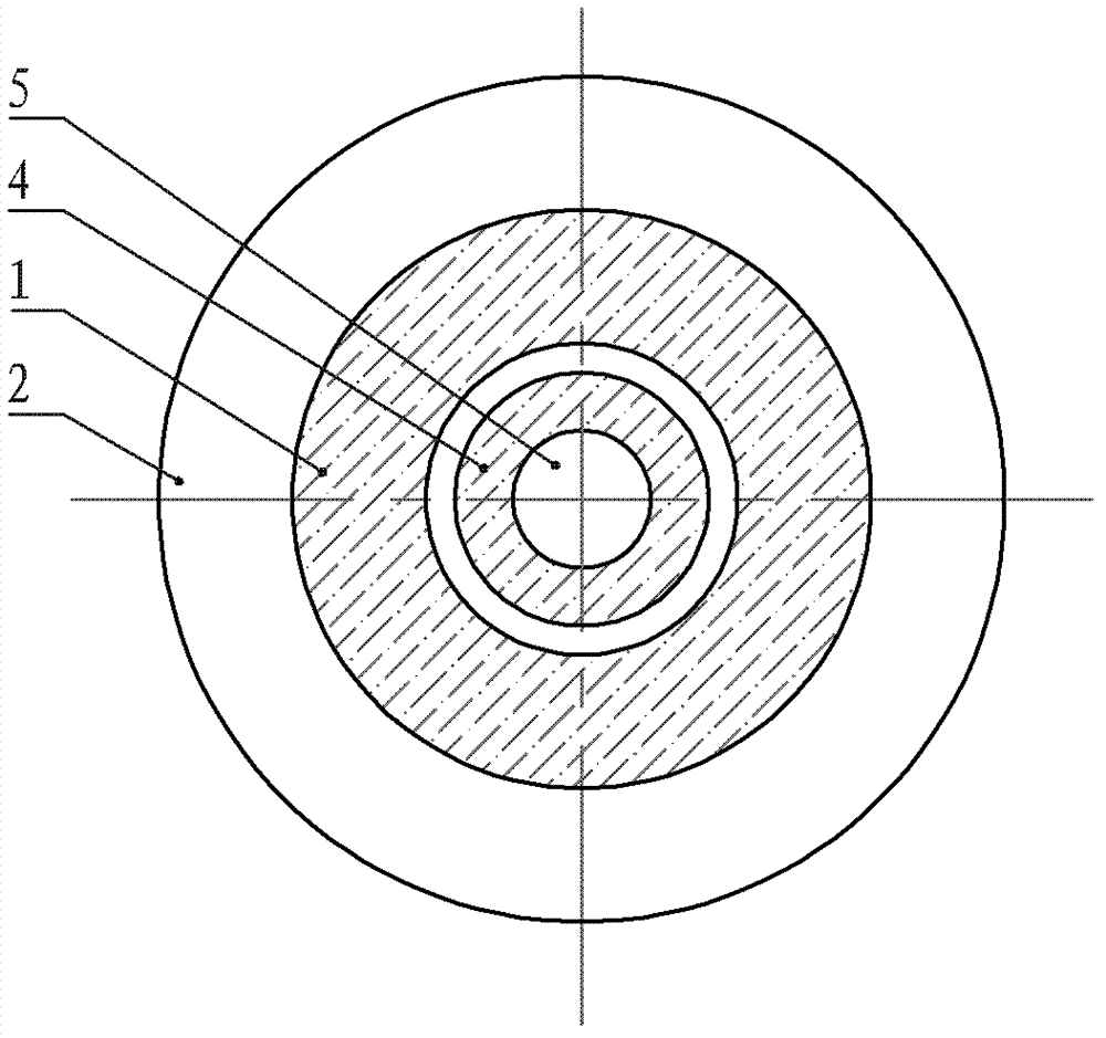
[0012] Specific Embodiments 1. The low thrust fluctuation linear permanent magnet synchronous motor described in this embodiment includes a primary, a secondary and an air gap, the secondary includes a secondary permanent magnet 4 and a yoke 5, and the primary includes an armature core 2 and an armature The winding 3 is characterized in that the primary also includes two primary permanent magnets 1; the two primary permanent magnets 1 are pasted and fixed on the front and rear ends of the armature core 2 respectively, and the magnetic field generated by each primary permanent magnet 1 The magnetic field generated by the opposite secondary permanent magnet array interacts, so that the two ends of the primary generate a force parallel to the direction of motion, and the directions of the forces generated by the two primary permanent magnets 1 located at both ends are opposite or opposite , and cancel each other out.

[0013] In this embodiment, the primary permanent magnet 1 is ...

specific Embodiment approach 2

[0015] Embodiment 2. This embodiment is a further limitation of the low thrust fluctuation linear permanent magnet synchronous motor described in Embodiment 1. In this embodiment, the two primary permanent magnets 1 are pasted and fixed on the armature core 2 respectively. The end faces of the front and rear ends of the motor are perpendicular to the moving direction of the motor mover.

[0016] The installation position of the primary permanent magnet 1 described in this embodiment is suitable for the case where the plane of the end of the armature core is perpendicular to the moving direction of the mover, that is, the plane where the end surface of the armature core is located is perpendicular to the moving direction of the mover.

[0017] see figure 1 As shown, this figure shows a schematic structural diagram of a linear motor with a flat structure. In the motor shown in this figure, the primary permanent magnet 1 is a flat structure.

[0018] see figure 2 with image...

specific Embodiment approach 3

[0019] Specific Embodiment 3. This embodiment is a further limitation of the low-thrust fluctuation linear permanent magnet synchronous motor described in Embodiment 1. In this embodiment, the two primary permanent magnets 1 are pasted and fixed on the armature core 2 respectively. On the end faces of the front and rear ends of the motor, the included angle between the end faces and the moving direction of the motor mover is less than 90°.

[0020] The installation position of the primary permanent magnet 1 described in this embodiment is suitable for the case where the plane of the end of the armature core is not perpendicular to the moving direction of the mover, that is, the end face of the armature core 2 is an inclined plane or arc.


PUM


Abstract

The invention provides an LPMSM (linear permanent magnet synchronous motor) with low-thrust fluctuation, belonging to the technical field of motors. The LPMSM is used for solving the fluctuation problem of an existing linear motor with low thrust. The LPMSM comprises two primary permanent magnets, wherein the two primary permanent magnets are fixed at the front and back ends of an armature core respectively. In the invention, the permanent magnets are added to end parts of a primary core, thus magnetic fields generated by the primary permanent magnets interact with magnetic fields generated by secondary permanent magnets, thereby reaching the purpose that acting forces at the front and back end parts of the LPMSM are offset mutually, and eliminating the positioning forces at the end parts; meanwhile, the unbalance between the magnetic fields at the primary end parts and intermediate magnetic fields can be reduced, and the differences between the electromotive forces generated by windings at the two primary ends and the electromotive forces generated by intermediate windings are decreased, thus lowering the fluctuation of electromagnetic forces.

Description

technical field [0001] The invention relates to a low-thrust fluctuation linear permanent magnet synchronous motor and belongs to the field of motors. Background technique [0002] Thrust fluctuations are the cause of vibration and noise of linear motors, especially at low speeds, and may also cause resonance, thereby deteriorating their servo operation characteristics. [0003] There are many reasons for the thrust fluctuation of the linear motor, including the thrust fluctuation caused by the end effect and the cogging effect, the influence of the manufacturing accuracy of the linear motor on the thrust output of the linear motor, and the linear motor caused by the mismatch between the phase current rectification waveform and the coil. The thrust output of the motor changes. [0004] For permanent magnet linear motors, due to the existence of the longitudinal end of the primary iron core and the permanent magnet of the stator, even when the motor winding is not energized,...

Claims


Application Information

Patent Timeline
Patent Type & Authority Patents(China)
IPC IPC(8): H02K41/03
Inventor 寇宝泉李春艳郭守仑赵斌超
Owner HARBIN INST OF TECH
Why Eureka
Try Eureka