
Voltage equalization modulation method and voltage equalization modulation device based on nearest level approximation

A recent technology of level approximation and modulation method, which is applied in the field of flexible power transmission and transformation, can solve the problems of large switching loss and many IGBT switching times

Active Publication Date: 2019-11-08
TBEA SUNOASIS
View PDF2 Cites 0 Cited by
  • Summary
  • Abstract
  • Description
  • Claims
  • Application Information

AI Technical Summary

Problems solved by technology

[0005] However, in the traditional voltage equalization control strategy, it is necessary to continuously determine the switching status of each sub-module according to the sorted capacitor voltage and the direction of the bridge arm current. Even if the capacitor voltage of the sub-module does not change much, switching may occur frequently Conversion, resulting in many switching times of IGBT in each bridge arm, and large switching loss

Method used


Image

  • Voltage equalization modulation method and voltage equalization modulation device based on nearest level approximation
  • Voltage equalization modulation method and voltage equalization modulation device based on nearest level approximation
  • Voltage equalization modulation method and voltage equalization modulation device based on nearest level approximation

Examples


Embodiment 1

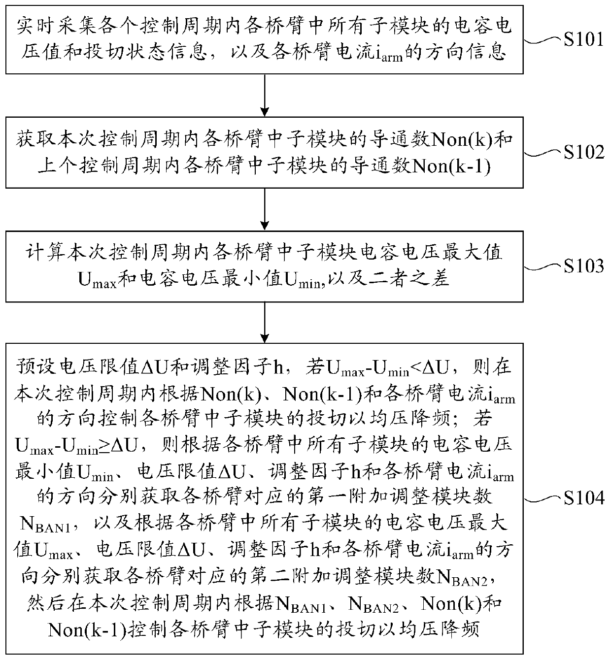
[0040] This embodiment provides a voltage equalization modulation method based on nearest level approximation. Such as figure 2 As shown, the voltage equalization modulation method includes the following steps S101 to S104.

[0041] S101. Real-time collection of capacitor voltage values ​​and switching status information of all sub-modules in each bridge arm in each control cycle, as well as the current i of each bridge arm arm direction information.

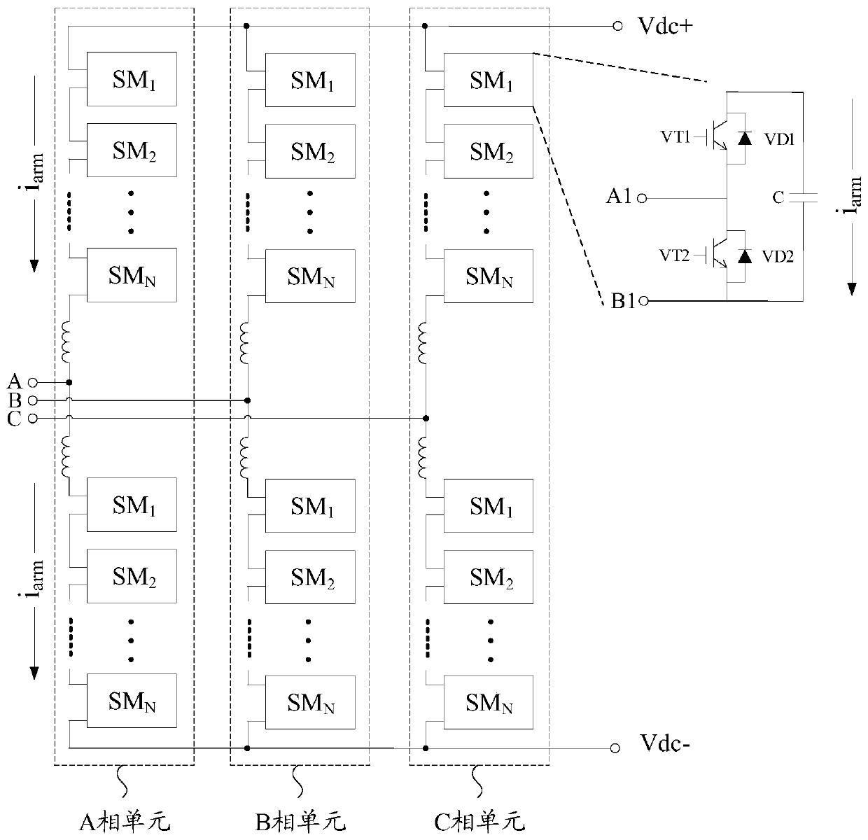
[0042] In this embodiment, the arm current i arm When the direction is downward, it is the positive direction (i arm >0), that is, the current i of each bridge arm arm It is the positive direction when the positive pole Vdc+ of the DC bus voltage flows to the negative pole Vdc- of the DC bus voltage. At this time, the capacitor of the sub-module that has been put into the bridge arm is charged; otherwise, the bridge arm current i arm When the direction is upward, it is the negative direction (i arm <0), at this time, disc...

Embodiment 2

[0117] This embodiment provides a voltage equalization modulation device based on nearest level approximation. Such as Figure 4 As shown, the voltage equalization modulation device includes an acquisition unit 100 , an acquisition unit 200 , a calculation unit 300 and a control unit 400 .

[0118] Wherein, the collection unit 100 is used to collect the capacitor voltage values ​​and switching status information of all sub-modules in each bridge arm in each control period, as well as the current i of each bridge arm armThe direction information; the acquisition unit 200 is used to obtain the conduction number Non(k) of each bridge arm neutron module in this control cycle and the conduction number Non(k-1 of each bridge arm neutron module in the last control cycle ), wherein k is an integer greater than 1; the calculation unit 300 is used to calculate the maximum value U of the sub-module capacitor voltage in each bridge arm in this control cycle max and the capacitor voltage...


PUM


Abstract

The present invention provides a common voltage modulation method based on the recent level, including: the default voltage limit ΔU and the adjustment factor H, if u max Puppet min <ΔU, in this control cycle, according to NON (K), NON (K‑1), and bridge arm current I arm The direction of the direction controls the cutting of the neutron modules of each bridge arm to reduce the frequency at average; if u max Puppet min ≥ ΔU, the minimum value of the capacitor voltage of the neutron module of each bridge arm min , Voltage limit ΔU, adjustment factor H and bridge arm current i arm Obtain the number of first additional adjustment modules corresponding to the bridge arm N BAN1 According to the maximum value of the capacitor voltage of the neutron module of each bridge arm max , Voltage limit ΔU, adjustment factor H and bridge arm current i arm Obtain the number of second additional adjustment modules corresponding to the bridge arm N BAN2 , Then according to n during this control cycle BAN1 N BAN2 , NON (K) and NON (K‑1) control the drop -cutting of the neutron modules of each bridge arm to reduce frequency.Correspondingly, a homogeneous modulation device is provided.The present invention can reduce the number of switches of power devices and reduce switching loss on the premise of meeting the mean pressure requirements.

Description

technical field [0001] The invention relates to the technical field of flexible power transmission and transformation, in particular to a voltage equalization modulation method based on nearest level approximation and a voltage equalization modulation device based on nearest level approximation. Background technique [0002] Compared with traditional voltage source converters, modular multilevel converters (Modular Multilevel Converter, MMC) have the advantages of good scalability, small harmonics, low switching frequency, and less requirements for consistent triggering of devices. The advantages are obvious, especially suitable for DC transmission applications. MMC-based flexible DC transmission technology is widely used in new energy transmission, urban expansion, regional power grid interconnection, and island power supply. Compared with traditional DC transmission technology, the advantages of flexible DC transmission technology are gradually highlighted. A number of fl...

Claims


Application Information

Patent Timeline
Patent Type & Authority Patents(China)
IPC IPC(8): H02M7/483
CPCH02M7/483H02M7/4835
Inventor 于向恩刘韬郝翔
Owner TBEA SUNOASIS
Learn More