Supercharge Your Innovation With Domain-Expert AI Agents!

Waterproof power source

A technology of power supply and waterproof glue, which is applied in the direction of electrical components, electrical equipment casings/cabinets/drawers, sealed casings, etc., can solve the problems of poor waterproof effect of waterproof power supplies, and achieve the effect of improving the waterproof effect

Active Publication Date: 2017-05-31
深圳市新全汉科技有限公司
View PDF10 Cites 0 Cited by
  • Summary
  • Abstract
  • Description
  • Claims
  • Application Information

AI Technical Summary

Problems solved by technology

That is to say, the waterproof effect of the above-mentioned traditional waterproof power supply is relatively poor.

Method used


Image

  • Waterproof power source
  • Waterproof power source

Examples


Embodiment Construction

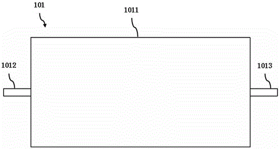
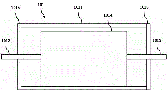
[0020] refer to figure 1 and figure 2 , figure 1 It is a schematic diagram of the waterproof power supply of the present invention, figure 2 It is a sectional view of the waterproof power supply of the present invention.

[0021] The waterproof power supply 101 of the present invention includes a housing 1011, a first side cover 1015, a second side cover 1016, a first waterproof rubber pad, a second waterproof rubber pad, a power input terminal 1012, a power output terminal 1013, a power circuit 1014, a control Devices, cooling components.

[0022] The housing is tubular. The first side cover is disposed at the first end opening of the housing. The second side cover is disposed at the second end opening of the housing. The first waterproof rubber pad is disposed between the casing and the first side cover. The second waterproof rubber pad is disposed between the casing and the second side cover. The power input end is arranged on the first side cover. The power inpu...


PUM


Abstract

The invention discloses a waterproof power source which comprises a tubular shell, a first side cover, a second side cover, a first waterproof rubber pad, a second waterproof rubber pad, a power source input end, a power source output end, a power source circuit, a controller and a heat radiating component. The first side cover is arranged at an opening of a first tail end of the shell, the second side cover is arranged at an opening of a second tail end of the shell, the first waterproof rubber pad is arranged between the shell and the first side cover, the second waterproof rubber pad is arranged between the shell and the second side cover, the power source input end is arranged on the first side cover, the power source output end is arranged on the second side cover, the first side cover, the second side cover and the shell surround to form a cavity, the power source circuit, the controller and the heat radiating component are all arranged in the cavity, the power source circuit is connected with the power source input end and the power source output end and connected with the controller, the heat radiating component is arranged between the power source circuit and the inner wall of the shell and connected with the power source circuit and the shell, and the controller is used for controlling turning on or off of the power source circuit. Waterproof effect of the waterproof power source can be improved.

Description

technical field [0001] The invention relates to the technical field of power supplies, in particular to a waterproof power supply. Background technique [0002] A traditional waterproof power supply generally includes a metal casing, a power circuit, a power input line and a power output line. Wherein, both the power input wire and the power output wire pass through the metal shell and are connected to the power circuit. [0003] However, after practice, the above-mentioned traditional waterproof power supply has the following defects: [0004] The water vapor outside the waterproof power supply will still enter the inside of the waterproof power supply. That is to say, the above-mentioned traditional waterproof power supply has poor waterproof effect. Contents of the invention [0005] The object of the present invention is to provide a waterproof power supply, which can improve the waterproof effect of the waterproof power supply. [0006] In order to solve the above...

Claims


Application Information

Patent Timeline
IPC IPC(8): H05K5/06
CPCH05K5/061H05K5/069
Inventor 周通明周敏王艳鸽
Owner 深圳市新全汉科技有限公司
Features
  • R&D
  • Intellectual Property
  • Life Sciences
  • Materials
  • Tech Scout
  • Unparalleled Data Quality
  • Higher Quality Content
  • 60% Fewer Hallucinations
Learn More