Disc brakes

A disc brake, disc brake technology, applied in the direction of brake type, brake components, axial brake, etc., can solve the problems of assembly and disassembly costs

Active Publication Date: 2019-08-13
WABCO EURO BVBA SPRL
View PDF3 Cites 0 Cited by
  • Summary
  • Abstract
  • Description
  • Claims
  • Application Information

AI Technical Summary

Problems solved by technology

The solution is also expensive in terms of assembly and disassembly

Method used


Image

  • Disc brakes
  • Disc brakes
  • Disc brakes

Examples


Embodiment Construction

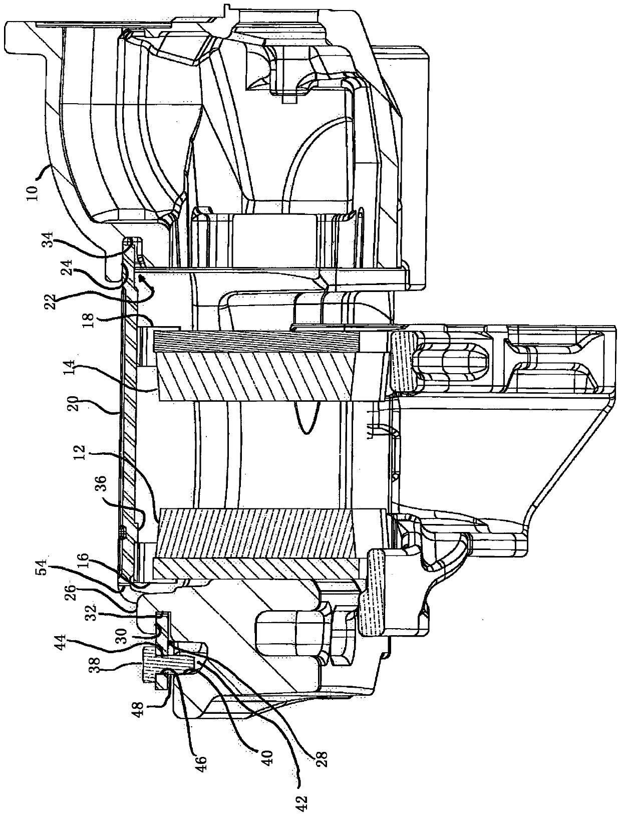
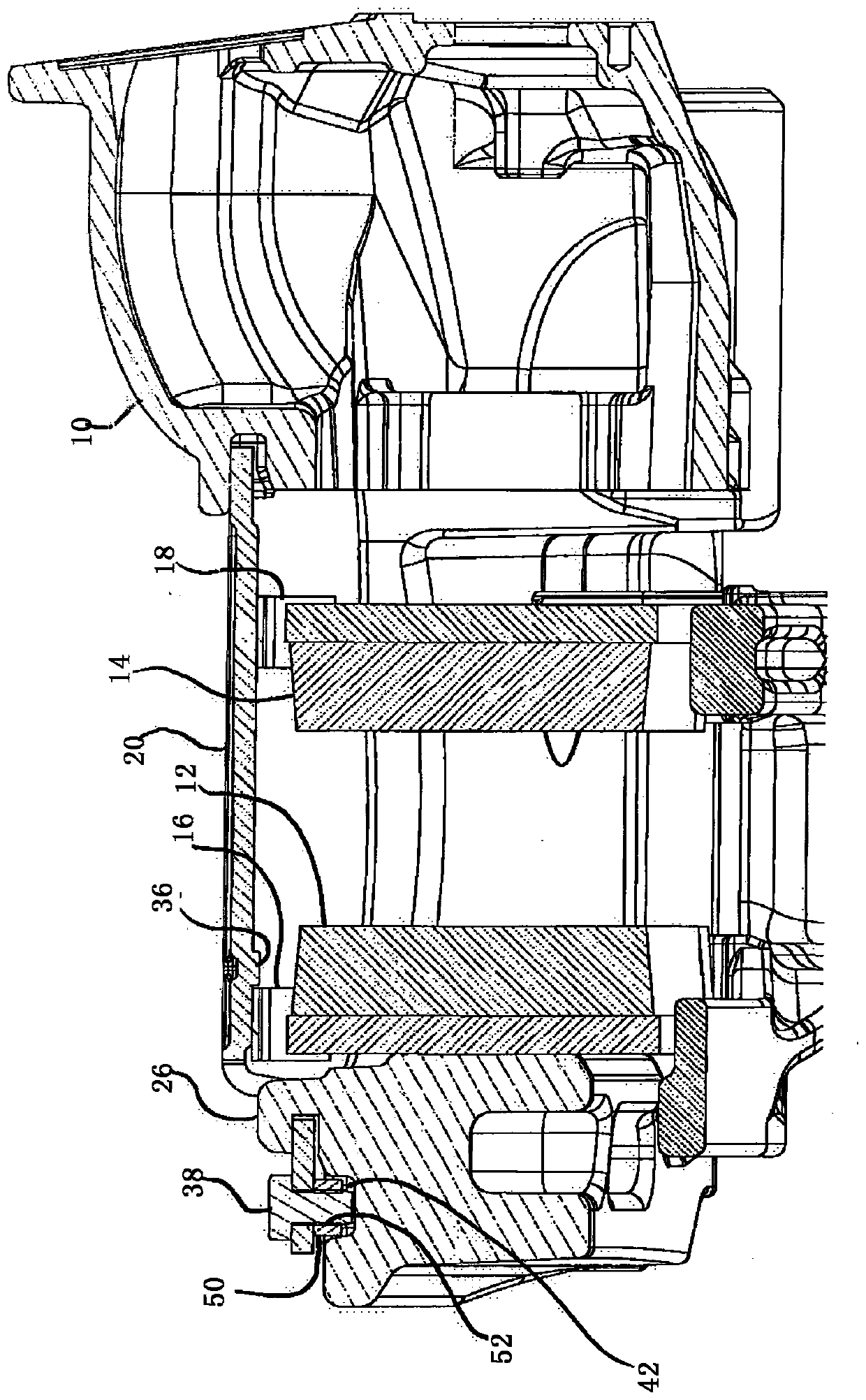
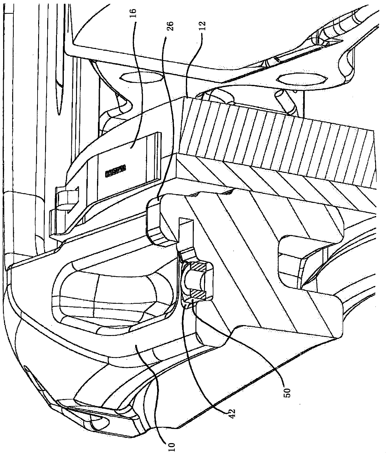
[0029] Belonging to the disc brake according to the invention is the figure 1 In the first embodiment shown there is a brake caliper 10 , two brake pads 12 , 14 , two hold-down springs 16 , 18 and hold-down bow 20 . Press the bow 20 in the radial direction, that is to say in figure 1 The middle is downward, so that the compression springs 16 and 18 are pretensioned. Between the brake pads 12 and 14 there is a brake disc (not shown). The pressing bow 20 also serves as a loss prevention device for the brake pads 12 and 14 , in particular in the event of a breakage of the pressing springs 16 , 18 .

[0030] The pressing bow is held on the pressing side in a slot 22 whose radially outer wall 24 absorbs the prestressing force.

[0031] On the rim side, a projection 26 is formed on the brake caliper 10 , which likewise has a slot 28 . The radially outer wall 30 of the slot 28 in turn serves to absorb the reaction force of the prestressing force.

[0032] In the two slots 22 and...


PUM


Abstract

A disc brake includes a brake caliper, a brake pad, a retaining spring holding the brake pad in a radial direction relative to a brake axis, a retaining bracket pretensioning the retaining spring in the radial direction, a first holder on the brake caliper configured to support the retaining bracket towards a radial outside, and a second holder on the brake caliper configured to support the retaining bracket radially towards the radial outside but not in an axial direction, the second holder comprising a stop. At least one of the first holder or the second holder has a stop acting in a first axial direction. The retaining bracket has at least one of a first protrusion that rests on the retaining spring in a second axial direction opposite the first axial direction and a second protrusion that rests on the brake caliper in the second axial direction.

Description

technical field [0001] The invention relates to a disc brake, in particular for commercial vehicles, having a brake caliper, at least one brake pad, a compression spring holding the brake pad in a radial direction with respect to the brake axis , a pressing bow that pretensions the pressing spring in the radial direction, a first holder on the brake caliper and a second holder on the brake caliper with a stop, the first holder being supported radially outwards The pressing bow, the stop radially outwards but not supporting the pressing bow in the axial direction, wherein the first or the second holder has a stop acting in the first axial direction. Background technique [0002] The above-mentioned pressing bow means that it must be a sufficiently bending-resistant component in order to prestress the pressing spring in the radial direction. A radial direction is not necessarily to be understood here as a direction which lies radially on the brake axis with mathematical preci...

Claims


Application Information

Patent Timeline
Patent Type & Authority Patents(China)
IPC IPC(8): F16D55/2255F16D65/097
CPCF16D55/2255F16D65/0978F16D55/225
Inventor 赫尔穆特·耶格尔马塞尔·卡尔姆巴赫
Owner WABCO EURO BVBA SPRL
Why Eureka
Try Eureka