
A method for realizing three-layer three-station injection molding of thick-walled parts

A realization method, three-station technology, applied in the direction of optical components, household appliances, other household appliances, etc., can solve the problems of long injection molding cycle and limited scope of application, so as to reduce the injection molding cycle and improve the precision of parts

Active Publication Date: 2019-02-15
HASCO VISION TECHNOLOGY CO LTD
View PDF4 Cites 0 Cited by
  • Summary
  • Abstract
  • Description
  • Claims
  • Application Information

AI Technical Summary

Problems solved by technology

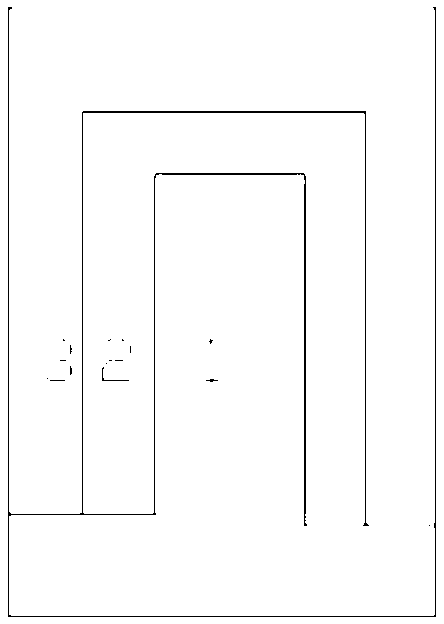
The usual multi-layer injection molding method adopts the method of layer-by-layer wrapping (see figure 1 ), this method is to control the suction wall (the suction wall refers to the product surface depression or internal cavity), the single injection molding cycle is long, and the scope of application is limited

Method used


Image

  • A method for realizing three-layer three-station injection molding of thick-walled parts
  • A method for realizing three-layer three-station injection molding of thick-walled parts
  • A method for realizing three-layer three-station injection molding of thick-walled parts

Examples


Embodiment Construction

[0031] First inject the middle layer (sequence number 1), then inject the upper side (serial number 2) of the described middle layer periphery, and finally inject the lower side (serial number 3) of the described middle layer periphery; set the fixed mold and the movable mold to realize injection molding (see figure 2 );

[0032] The specific steps are:

[0033] (1) No. 1 fixed mold and No. 1 moving mold are injected into the middle layer;

[0034] (2) The middle layer stays on the No. 1 movable mold side, rotates 120 degrees, and closes the mold;

[0035] (3) No. 1 fixed mold and No. 3 dynamic mold are injected into the middle layer; the middle layer of the mold opening is left on the side of No. No. fixed mold; reverse rotation 120 degrees;

[0036] (4) No. 1 fixed mold and No. 1 dynamic mold injection middle layer are opened and the middle layer is left on the side of No. 1 dynamic mold; No. 2 fixed mold and No. 2 dynamic mold are injected on the lower surface of the dy...


PUM


Abstract

The invention discloses an implementing method of a three-layer three-position injection molding for a thick-wall part. The implementing method comprises the following steps: the injection molding sequence is as follows: firstly performing injection molding on a middle layer, then performing injection molding on the upper side of the periphery of the middle layer and finally performing injection molding on the lower side of the periphery of the middle layer; setting fixed molds and movable molds to realize injection molding; arranging the fixed molds uniformly in three positions, wherein the fixed molds are spaced at 120 degrees, and arranging the movable molds uniformly in three positions, wherein the movable molds are spaced at 120 degrees. By repeated rotation, the movable and fixed molds of a product stand alternately, so the injection molding period is shortened and the part precision is improved.

Description

technical field [0001] The invention relates to the field of automobile manufacturing, in particular to a scheme for realizing layering of a thick-walled light guide for molds.. Background technique [0002] Light guides are an important part of automotive lighting. In recent years, more and more automobile lights use light guides as inner light distribution mirrors. Using light guides as inner light distribution mirrors can not only reduce the cost of lights, but also reduce energy consumption while ensuring the same function. In addition, The style of the headlights is also beautiful because of the use of light guide strips. [0003] As a kind of light guide, the thick-walled light guide is a structural member that guides the light emitted by the light-emitting diode from the circuit board to the light-emitting position. This structural member is generally made of PC (polycarbonate) material, or PMMA (polymethyl Methyl acrylate) material. [0004] Due to the long coolin...

Claims


Application Information

Patent Timeline
Patent Type & Authority Patents(China)
IPC IPC(8): B29C45/06B29C45/16B29L9/00B29L11/00
CPCB29C45/062B29C45/1628B29C45/1642B29C2045/067B29L2009/00B29L2011/0075
Inventor 朱叶琪
Owner HASCO VISION TECHNOLOGY CO LTD
Learn More