Application method for magnetic card

A magnetic card and support rod technology, which is applied in the field of card reader, can solve the problems of card reader damage, card reader loosening, material waste, etc., and achieve the effect of improving clamping efficiency, convenient fixed installation and maintenance and replacement

Inactive Publication Date: 2017-06-06
重庆文达和科技有限公司
View PDF0 Cites 0 Cited by
  • Summary
  • Abstract
  • Description
  • Claims
  • Application Information

AI Technical Summary

Problems solved by technology

During driving, especially on bumpy roads, the body shakes violently, which makes the fixing of the card reader easy to loosen, which in turn leads to damage or direct failure of the card reader; and the existing card reader is fixed by welding or clamps. , when replacing or repairing the credit card machine, it can only be dismantled by cutting or violent destruction, resulting in a large waste of materials

Method used


Image

  • Application method for magnetic card

Examples


Embodiment 1

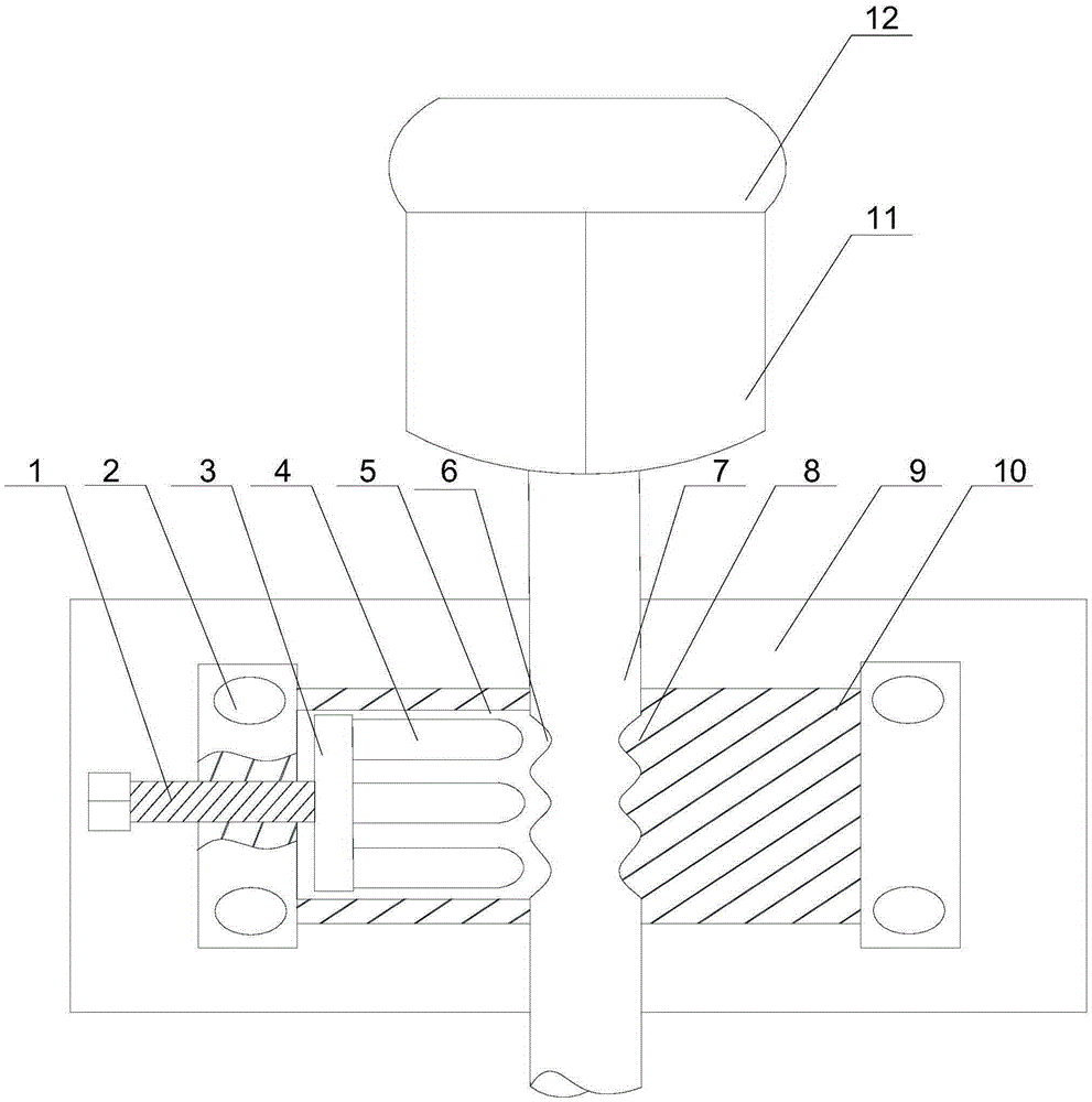
[0024] Such as figure 1 As shown, this embodiment includes the following steps:

[0025] A Weld the support rod or fix it in other ways to the toll point of the front door of the bus, and the mounting seat is rotated and installed on the support rod through the threaded through hole;

[0026] B According to the appropriate height, when the mounting seat covers the first spiral groove on the support rod from top to bottom, stop the movement of the mounting seat, and manually adjust the screw so that the bottom plate can move freely in the movable cavity until the clamping rod The end engages with a helical groove, thereby enabling the fastening of the mount to the support rod;

[0027] C The upper and lower ends and the middle of the support rod are respectively provided with threads and spiral grooves. By cooperating with the mounting seat, the double connection and fixation between the support rod and the mounting seat is realized, and the threads of the mounting seat and th...

Embodiment 2

[0032] Such as figure 1 As shown, on the basis of Embodiment 1, this embodiment also includes a mounting plate 9, a plurality of mounting holes 2 are opened at both ends of the mounting base 10, and the mounting plate 9 is arranged on the upper plate of the mounting base 10 through the mounting holes 2. Set on the mounting base 10 through the threaded hole. The traditional card reader is fixed on the support frame by welding, so that the support frame will be directly damaged when the card reader is damaged or maintained, resulting in a waste of resources and an increase in cost. On the seat 10, the card reader is installed on the fixed plate, and the fixing method can also be fixed by bolts and other movable connection methods, so that in each maintenance and replacement process, the mounting seat 10 can also be used for fixed connection and recycled to reduce The cost of using the credit card machine.

[0033] The end of the clamping rod 4 is U-shaped, conical or tooth-shape...


PUM


Abstract

The invention publishes an application method for a magnetic card. The method comprises the following steps that a support rod is welded or fixed at a cashier which is located at the front door of a bus, a mounting base is rotatedly arranged on the support rod through a tapped through hole; when a first spiral groove on the support rod form up to down is cover through the mounting base, the motion of the mounting base is stopped, a screw is adjusted by hand, which makes a baseboard move freely in a active cavity until the top of the support rod is meshed with the spiral groove, so that the mounting base is achieved to be tightly fixed on the support rod; the both ends and the middle of the support rod are respectively provided with the screw thread and the spiral groove, dual connection and fixation between the support rod and the mounting base are achieved according to the coordination of the mounting base, which is convenient for the operator to perform fixed installation quickly and maintenance and change. Especially during rush hours, a credit card machine located at the top end of the support rod is formed a cyclic structure for multiple readers, which means the card can be swiped within 360 DEG.

Description

technical field [0001] The invention relates to a card reader, in particular to a method for using a magnetic card. Background technique [0002] The non-contact IC card bus toll system is the most advanced bus toll management system at present. It adopts the cutting-edge technology of radio frequency identification and is designed in combination with modern management methods. It has contact-free, loss-free, advanced technology, and system scalability. It is the best choice for public transport units to improve their management level and realize electronic control. It is widely used in urban public transport, vehicle charges for enterprises and institutions, school special vehicle charges, community special vehicle charges, etc. [0003] The bus card reader is the core construction part of the urban bus card and a part of the intelligent bus I system. It is composed of a vehicle toll terminal and a background management system, which greatly improves the service level of th...

Claims


Application Information

Patent Timeline
Patent Type & Authority Applications(China)
IPC IPC(8): B60R11/00
CPCB60R11/00B60R2011/0003B60R2011/0071
Inventor 向美友
Owner 重庆文达和科技有限公司
Why Eureka
Try Eureka