
A Contact Calculation Method for Hypoid Gears Considering the Effect of Misalignment

A technology of hypoid gear and calculation method, applied in design optimization/simulation, geometric CAD, special data processing application, etc. And other issues

Active Publication Date: 2020-04-07
TSINGHUA UNIV +1
View PDF1 Cites 0 Cited by
  • Summary
  • Abstract
  • Description
  • Claims
  • Application Information

AI Technical Summary

Problems solved by technology

However, when using the finite element contact calculation method to analyze a gear transmission system containing multiple rolling bearings, considering that there is a contact relationship between each roller of the bearing and the raceway, limited by the convergence and calculation scale, the existing Research often ignores other transmission system components such as rolling bearings and housings when modeling, and only performs finite element contact calculations for a single pair of gear pairs, without considering the influence of gear misalignment caused by the deformation of the transmission system on the gear contact calculation
In order to realize the numerical simulation of the gear transmission system containing multiple rolling bearings, the analytical nonlinear bearing unit and the equivalent meshing unit of the hypoid gear are applied to the gear transmission system model, but the equivalent meshing parameters of the hypoid gear are usually According to the theoretical formula, the influence of the tooth surface friction and the nonlinear contact state of the gear is not considered, and there is no effective means to accurately reflect the gear misalignment calculated by the static calculation of the transmission system in the gear finite element contact calculation model

Method used


Image

  • A Contact Calculation Method for Hypoid Gears Considering the Effect of Misalignment
  • A Contact Calculation Method for Hypoid Gears Considering the Effect of Misalignment
  • A Contact Calculation Method for Hypoid Gears Considering the Effect of Misalignment

Examples


Embodiment Construction

[0073] The present invention will be described in detail below in conjunction with the accompanying drawings and embodiments.

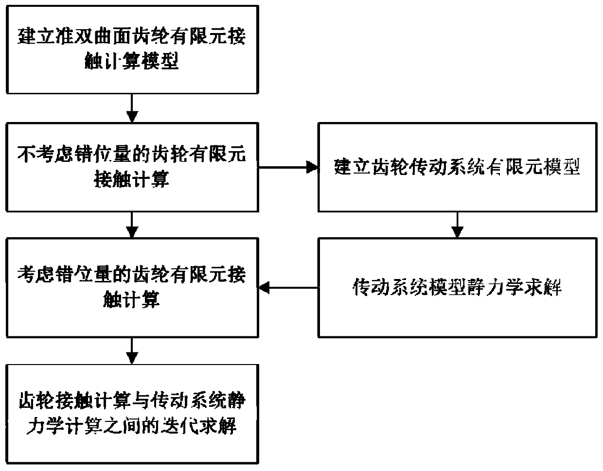
[0074] Such as figure 1 As shown, the present invention provides a hypoid gear contact calculation method considering the influence of misalignment, which specifically includes the following steps:

[0075] 1) Establish a hypoid gear finite element contact calculation model.

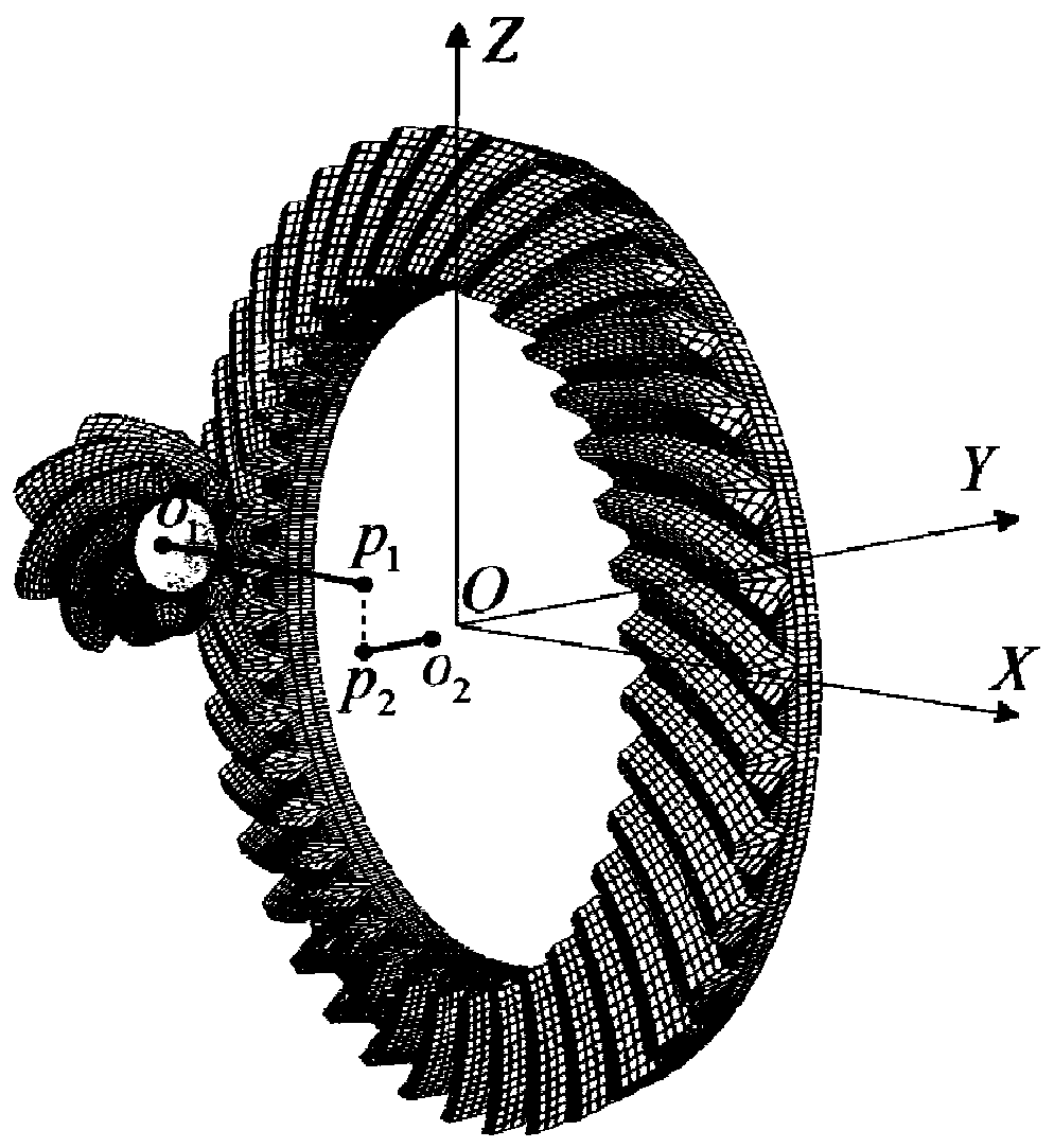
[0076] Such as figure 2 As shown, the finite element models of the small wheel and the large wheel are respectively established, wherein the axis of the small wheel is parallel to the X axis of the global coordinate system, the axis of the large wheel is parallel to the Y axis of the global coordinate system, and the small wheel is offset along the Z axis of the global coordinate system. Establish the center node o at the centroid positions of the small wheel and the big wheel respectively 1 and o 2 , using a rigid link element to couple the central node to the volume eleme...


PUM


Abstract

The invention relates to a hypoid gear contact calculation method considering a misalignment quantity influence. The method comprises the following steps of constructing a hypoid gear finite element contact calculation model, carrying out gear finite element contact calculation not considering the misalignment quantity influence and calculating an equivalent meshing force direction unit vector and an equivalent meshing node coordinate, constructing a gear transmission system finite element model, calculating a gear transmission system finite element statics model and calculating a gear center beam element node displacement vector and a misalignment quantity reference node displacement vector, changing orientation of the hypoid gear finite element contact calculation model, carrying out gear finite element contact calculation considering the misalignment quantity influence, carrying out an iterative solution between the gear finite element contact calculation considering the misalignment quantity influence and transmission system finite element model statics solution, calculating a statics equilibrium state of the gear finite element contact calculation model and the transmission system finite element model, and calculating a hypoid gear contact calculation result accurately considering the misalignment quantity influence.

Description

technical field [0001] The invention relates to a gear contact calculation method, in particular to a hypoid gear contact calculation method considering the influence of misalignment. Background technique [0002] Hypoid gears are widely used in mechanical transmission systems such as drive axles and gearboxes. The deformation of the gear transmission system under load will cause gear misalignment and lead to changes in the meshing state of the gears. In order to ensure that the hypoid gear design meets the performance requirements, it is usually necessary to perform Loaded Tooth Contact Analysis (LTCA, Loaded Tooth Contact Analysis). Using commercial finite element analysis software such as Abaqus can effectively realize the contact calculation of gears. However, when using the finite element contact calculation method to analyze a gear transmission system containing multiple rolling bearings, considering that there is a contact relationship between each roller of the beari...

Claims


Application Information

Patent Timeline
Patent Type & Authority Patents(China)
IPC IPC(8): G06F30/23G06F30/17
CPCG06F30/17G06F30/23
Inventor 范子杰周驰王琪桂良进丁炜琦
Owner TSINGHUA UNIV
Learn More