
A two-dimensional magneto-optical trap device

A magneto-optical trap and the other side technology, applied in the field of two-dimensional magneto-optical trap devices, can solve the problems of relatively high laser power requirements, large optical power loss, and large space size, and achieve small lateral divergence angles and compact structural design , small size effect

Active Publication Date: 2018-10-12
FLIGHT AUTOMATIC CONTROL RES INST
View PDF5 Cites 0 Cited by
  • Summary
  • Abstract
  • Description
  • Claims
  • Application Information

AI Technical Summary

Problems solved by technology

The optical path of this scheme is relatively complicated, the space size is large, and the optical power loss is relatively large due to the use of too many optical devices, and the requirements for laser power are relatively high, so it is not suitable for miniaturization and engineering applications.

Method used


Image

  • A two-dimensional magneto-optical trap device
  • A two-dimensional magneto-optical trap device
  • A two-dimensional magneto-optical trap device

Examples


Embodiment Construction

[0016] The present invention will be further described below in conjunction with accompanying drawing:

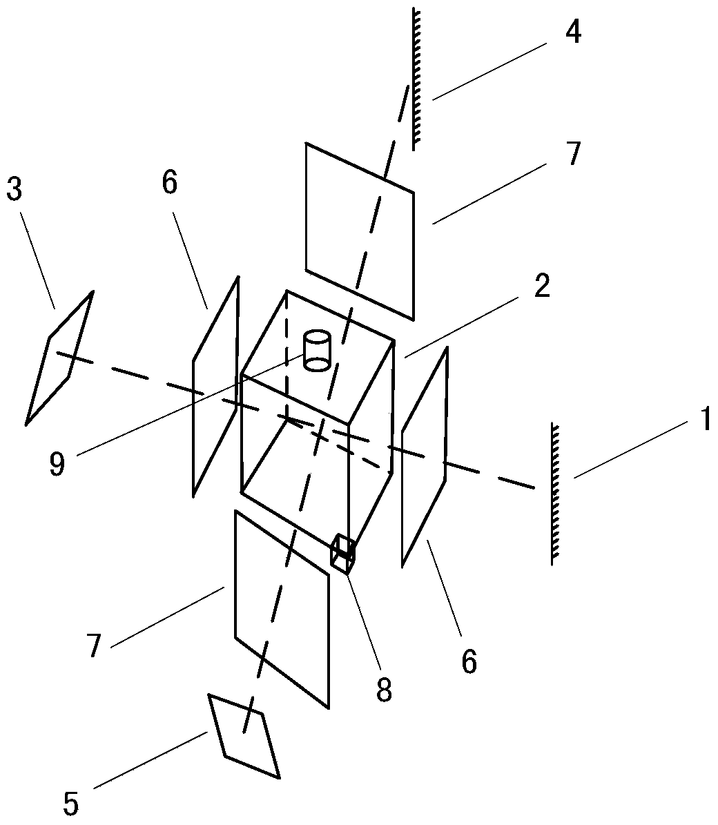
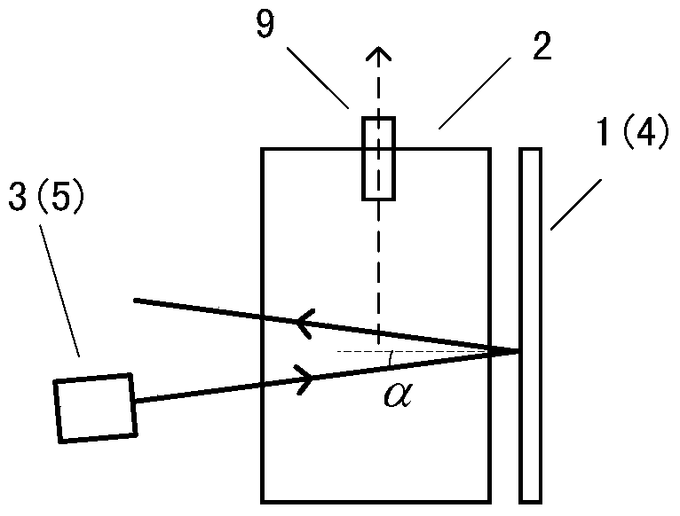
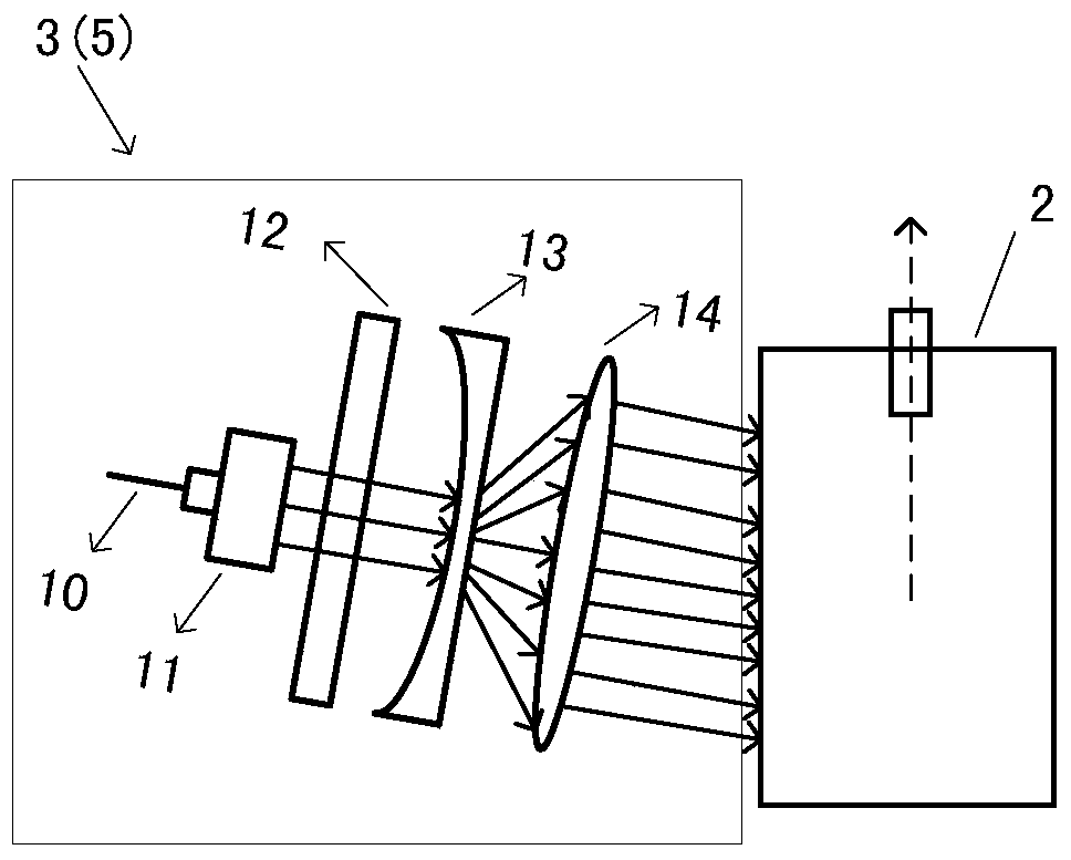
[0017] see figure 1 The two-dimensional magneto-optical trap device of the present invention includes a first reflector 1, a vacuum chamber 2, a first laser collimation and beam expansion system 3, a second reflection mirror 4, a second laser collimation and beam expansion system 5, and a first pair 6 , the second coil pair 7 . Wherein, the first laser collimation and beam expansion system 3 is located on one side of the first incident surface of the vacuum cavity, and the exit direction is inclined to the surface of the vacuum cavity, and the first mirror 1 is located on the other side of the vacuum cavity 2, collimated with the first laser Beam expander system 3 corresponds. The second laser collimation and beam expansion system 5 is located on one side of the second incident surface of the vacuum cavity, and the exit direction is inclined to the surface of the vacuum c...


PUM


Abstract

The invention belongs to the atom cooling technologies, and discloses a 2 dimensional magneto-optical trap apparatus which is reduced in size and mains high-velocity stream for a 3 dimensional magneto-optical trap. The invention provides a 2 dimensional magneto-optical trap apparatus which includes a vacuum cavity having an atom source, a first laser alignment beam expanding system which is intended for generating a cooling beam, a first reflector, a second laser alignment system which is intended for generating another cooling beam, a second reflector, two pairs of anti-Helmholtz coils which are intended for generating a magnetic field. The incoming direction of the cooling beam is tilted at a certain angle with respect to the long shaft direction off the vacuum cavity, such that the cooling beam generates a light intensity component in the long shaft direction of the vacuum cavity. The light intensity component serves as effective pushing light. And a cooling sub-beam having high flux is obtained without an extra pushing light. According to the invention, the 2 dimensional magneto-optical trap apparatus can obtain the cooling sub-beam which meets requirements for low longitudinal speed, narrow distribution of longitudinal speed and large flux of atoms, has a simple structure and small size, and realizes reduction in sizes of the magneto-optical trap atom cooling systems.

Description

technical field [0001] The invention belongs to atom cooling technology, and in particular relates to a two-dimensional magneto-optical trap device that provides a miniaturized, continuous high-speed flow for a three-dimensional magneto-optic trap. Background technique [0002] With the development of laser cooling technology, especially the emergence and maturity of laser cooling atom technology, the temperature of atoms can be reduced to the order of μK or even nK, the coherence of atoms is greatly improved, and the research and application of cold atoms has become a hot spot. Significant progress has also been made in research on atomic inertial devices such as cold atomic gyroscopes, atomic accelerometers, atomic gravimeters, and atomic fountains. As the carrier of these studies, cold atom sources with narrow velocity distribution, small divergence angle, and high flux have become the focus of research. [0003] The preparation technology of the cold atom source usually...

Claims


Application Information

Patent Timeline
Patent Type & Authority Patents(China)
IPC IPC(8): G21K1/00
CPCG21K1/006
Inventor 闻茗萱刘元正李俊雷兴李攀
Owner FLIGHT AUTOMATIC CONTROL RES INST
Learn More