Optical device, optical system, display device, display equipment, and display system
An optical device and display device technology, applied in optics, optical components, instruments, etc., can solve the problems of large occupancy, heavy weight, reduced ease of use, etc., and achieve the effect of compact optical path structure, low cost, small size and light weight
- Summary
- Abstract
- Description
- Claims
- Application Information
AI Technical Summary
Problems solved by technology
Method used
Image
Examples
no. 1 example
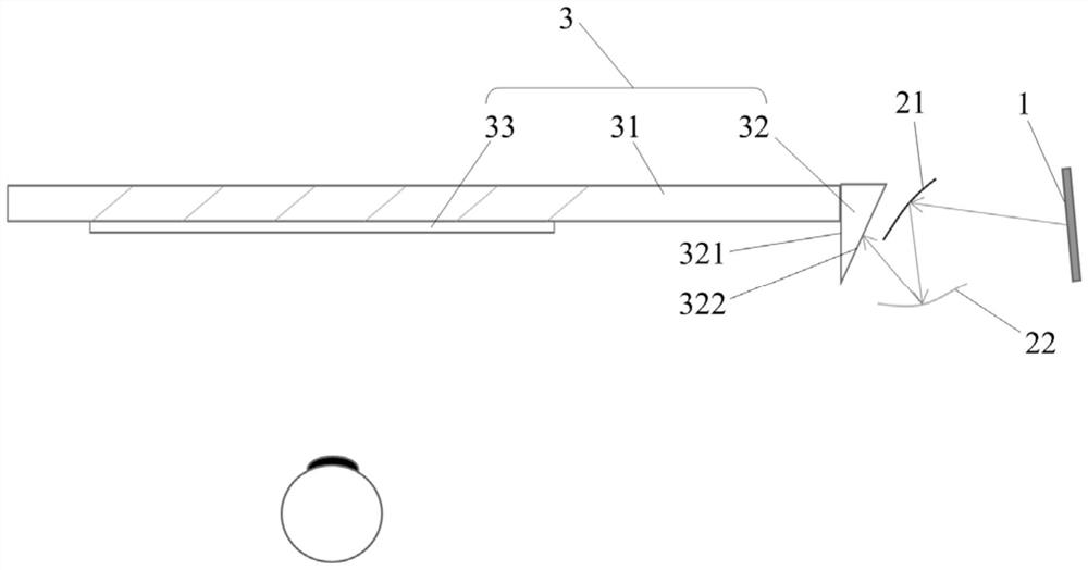
[0032] figure 1 Shown is a schematic structural diagram of a near-eye display optical device provided by the first embodiment of the present invention. figure 1 The straight lines with arrows in the middle indicate the general direction of the light path.
[0033] The invention provides a near-eye display optical device, such as figure 1 As shown, it includes an image source 1 , a first mirror 21 , a second mirror 22 and a light guiding mechanism 3 . The image source 1 emits image light. The first reflector 21 is located in the light emitting direction of the image source 1, and the second reflector 22 is located in the reflective direction of the first reflector 21. The first reflector 21 and the second reflector 22 are jointly configured to: shape the image light into Collimate the image light. The light guide mechanism 3 is installed on the light emitting direction of the second reflector 22, and the light guide mechanism 3 is configured to: couple the collimated image ...
no. 2 example
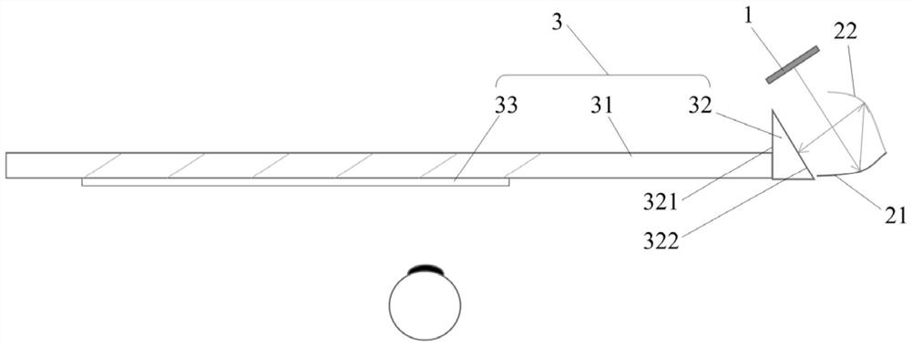
[0043] figure 2 Shown is a schematic structural diagram of a near-eye display optical device provided by the second embodiment of the present invention. figure 2 The straight lines with arrows in the middle indicate the general direction of the light path. The difference between the embodiment and the first embodiment is: as figure 2 As shown, one side of the first reflecting mirror 21 is in contact with one side of the second reflecting mirror 22 . Other structures and designs of this embodiment can adopt the same structure and design as that of the first embodiment.
[0044] When in use, since one side of the first reflector 21 is in contact with one side of the second reflector 22, the total volume occupied by one side of the first reflector 21 and the second reflector 22 can be smaller, and the first reflector 21 The folded optical path formed by the second reflecting mirror 22 is more compact. The angle between the normal at the geometric center of the first reflec...
no. 3 example
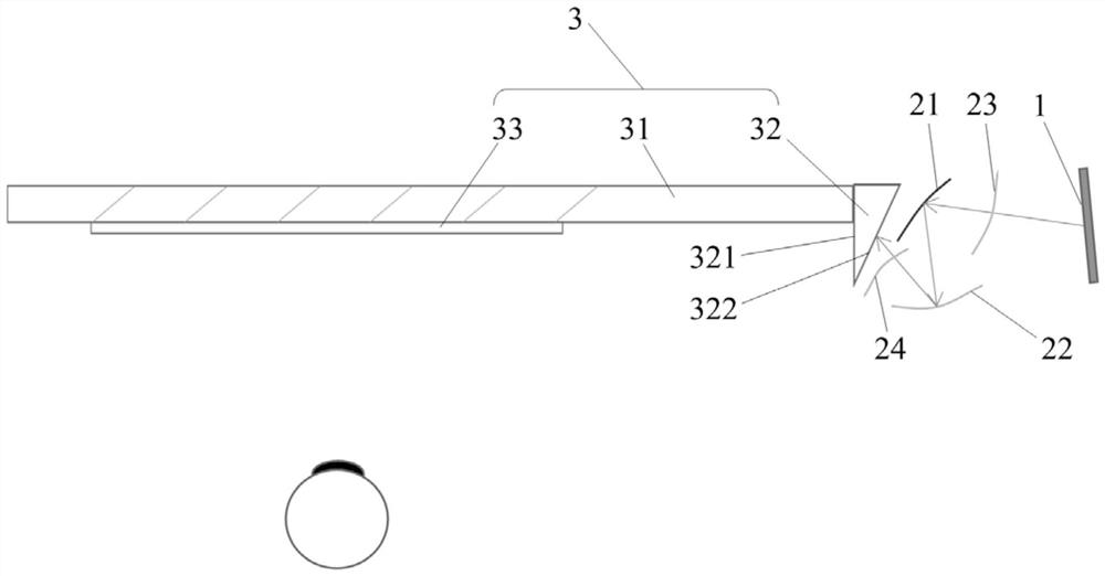
[0046] image 3 Shown is a schematic structural diagram of a near-eye display optical device provided in the first embodiment of the present invention with a transmission surface. Figure 4 Shown is a schematic structural diagram of a near-eye display optical device provided in the second embodiment of the present invention with a transmission surface. image 3 and Figure 4 The straight line with the arrow in the middle indicates the approximate propagation direction of the light path. Such as image 3 and Figure 4 As shown, the near-eye display optical device further includes a first transmission surface 23 , and the first transmission surface 23 is arranged on the optical path between the image source 1 and the first reflection mirror 21 .
[0047] In use, the first transmission surface 23 refracts the image light emitted by the image source 1 , thereby changing the optical path of the image light emitted by the image source 1 . Through the first transmission surface ...
PUM
 Abstract
Description
Claims
Application Information
 - R&D
- Intellectual Property
- Life Sciences
- Materials
- Tech Scout
- Unparalleled Data Quality
- Higher Quality Content
- 60% Fewer Hallucinations
Browse by: Latest US Patents, China's latest patents, Technical Efficacy Thesaurus, Application Domain, Technology Topic, Popular Technical Reports.
© 2025 PatSnap. All rights reserved.Legal|Privacy policy|Modern Slavery Act Transparency Statement|Sitemap|About US| Contact US: help@patsnap.com


