Supercharge Your Innovation With Domain-Expert AI Agents!

Sheath flow detection system and sheath flow control method

A technology of detection system and control method, which can be applied to measurement devices, biological tests, material inspection products, etc., can solve the problems of pollution of detection results and interference detection, and achieve the effect of avoiding influence.

Active Publication Date: 2017-06-09
SONOSCAPE MEDICAL CORP
View PDF6 Cites 8 Cited by
  • Summary
  • Abstract
  • Description
  • Claims
  • Application Information

AI Technical Summary

Problems solved by technology

[0004] 1. Due to the structural characteristics of the reaction pool, using the cleaning solution to flush the inner wall from top to bottom may not be able to fully clean the lower part covered by liquid;
[0005] 2. The sample transmission pipeline only uses the subsequent sample transmission to flush the previous residual liquid, which may cause pollution to the subsequent test results;
[0006] 3. The waste liquid is directly connected to the waste liquid pipe to be emptied, and it is easily affected by other negative pressure in the waste liquid pipe during the detection process, which interferes with the detection of this part

Method used


Image

  • Sheath flow detection system and sheath flow control method
  • Sheath flow detection system and sheath flow control method

Examples


Embodiment 1

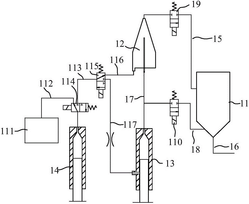
[0049] see figure 1 , the present invention provides a sheath flow detection system, including a first reaction pool 11, a first sheath flow counting chamber 12, a first sample injector 13 and a first sheath fluid injector 14; the first sheath flow counting chamber 12 includes a first sheath flow counting chamber 12 A sheath chamber, a diluent interface and a first sample needle extending into the first sheath chamber, the first sheath flow counting chamber 12 can be counted by a detector; the first sample injector 13 can be obtained from the first reaction The liquid is sucked in the pool 11 and injected into the first sheath chamber through the first sample needle; the first sheath liquid injector 14 can inject the diluent into the first sheath chamber through the diluent interface; the first sheath flow counting chamber 12 is provided with Connected to the first waste liquid pipe 15 of the first reaction pool 11 , the first reaction pool 11 is provided with a first negative...

Embodiment 2

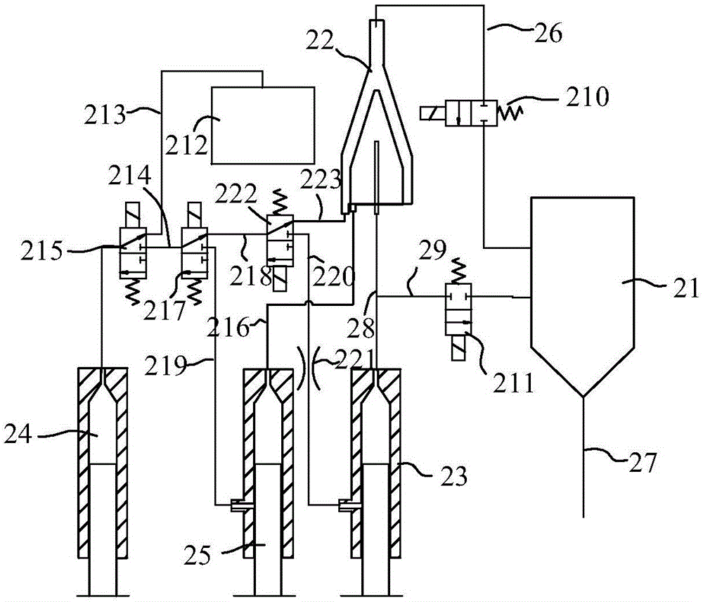
[0061] see figure 2 , the present invention also discloses another sheath flow detection system, comprising a second reaction pool 21, a second sheath flow counting chamber 22, a second sample injector 23, a second sheath fluid injector 24 and a third sheath fluid injector 25, the The second sheath flow counting chamber 22 includes an inner sheath chamber, an outer sheath chamber, an inner diluent interface communicated with the inner sheath chamber, an outer diluent interface communicated with the outer sheath chamber, and a second sample extending into the inner sheath chamber The second sample injector 23 can draw liquid from the second reaction pool 21 and inject it into the inner sheath chamber through the second sample needle, and the second sheath liquid injector 24 can inject the diluent into the outer sheath chamber through the outer diluent interface, The third sheath liquid injector 25 can inject diluent into the inner sheath chamber through the inner diluent inter...


PUM


Abstract

The invention discloses a sheath flow detection system and a sheath flow control method, and is applied to the technical field of flow cytometry detection. The sheath flow detection system comprises a first reaction pool, a first sheath flow counting chamber, a first sample injection syringe and a first sheath liquor injection syringe. The first sheath flow counting chamber comprises a first sheath chamber, a diluent connector and a first sample needle, the first sample needle extends into the first sheath chamber, liquor can be sucked from the first reaction pool by the first sample injection syringe and can be injected into the first sheath chamber via the first sample needle, diluent can be injected into the first sheath chamber by the first sheath liquor injection syringe via the diluent connector, a first waste liquor pipe which is connected into the first reaction pool is arranged on the first sheath flow counting chamber, and a first negative-pressure drain opening is formed in the first reaction pool. The sheath flow detection system and the sheath flow control method have the advantages that influence of pressures of waste liquor drain modules on fluid inside the sheath flow counting chamber can be prevented, waste liquor generated during detection is already diluted for many times, and accordingly can be used as the diluent for washing liquor pipes.

Description

technical field [0001] The invention is used in the technical field of flow cytometry, and in particular relates to a sheath flow detection system and a sheath flow control method. Background technique [0002] The current flow cytometry detection devices basically use the principle of flow cytometry to classify or count cells or other types of particles. Among them, sheath flow technology or flow focusing technology is the core technology of flow cytometry device. From a functional point of view, sheath flow technology not only needs to quickly establish a stable sample flow in a short period of time, but also needs to fully and effectively clean the fluid pipeline and reaction pool after the test is completed. [0003] The existing technology is to only flush the sheath flow counting chamber and the downstream pipeline in one direction after the sheath flow detection is completed; for the sample transmission pipeline, only the latter sample transmission process can be use...

Claims


Application Information

Patent Timeline
Patent Type & Authority Applications(China)
IPC IPC(8): G01N33/49
CPCG01N33/4915
Inventor 白新梅喻小磊涂艳玲
Owner SONOSCAPE MEDICAL CORP
Features
  • R&D
  • Intellectual Property
  • Life Sciences
  • Materials
  • Tech Scout
  • Unparalleled Data Quality
  • Higher Quality Content
  • 60% Fewer Hallucinations
Learn More