A combined cooling type power distribution cabinet

A power distribution cabinet and heat dissipation technology, which is applied in the substation/distribution device casing, electrical components, substation/switch layout details, etc. and other problems, to achieve the effect of good cooling effect

Inactive Publication Date: 2018-10-09
HENAN HONGDA TELECOM EQUIP
View PDF7 Cites 0 Cited by
  • Summary
  • Abstract
  • Description
  • Claims
  • Application Information

AI Technical Summary

Problems solved by technology

[0002] The power distribution cabinet is a relatively common type of electrical equipment. The power distribution cabinet is used in many occasions. Some power distribution cabinets are installed outdoors. Outdoor power distribution cabinets are often exposed to sunlight, and the temperature inside the cabinet is often relatively high. There are many kinds of electrical components installed inside the upper power distribution cabinet. These electrical components emit a lot of heat when they work, which further increases the temperature inside the cabinet. If the heat is not dissipated in time, it will affect the internal temperature of the cabinet. The normal operation of electrical components, and the existing power distribution cabinets are generally integrated factory design. When the internal components of the power distribution cabinet need to be repaired, it needs to be completely disassembled, which is troublesome. In view of this, we propose a combined heat dissipation type Distribution Cabinet

Method used


Image

  • A combined cooling type power distribution cabinet
  • A combined cooling type power distribution cabinet
  • A combined cooling type power distribution cabinet

Examples


Embodiment Construction

[0023] The following will clearly and completely describe the technical solutions in the embodiments of the present invention with reference to the accompanying drawings in the embodiments of the present invention. Obviously, the described embodiments are only some, not all, embodiments of the present invention. Based on the embodiments of the present invention, all other embodiments obtained by persons of ordinary skill in the art without making creative efforts belong to the protection scope of the present invention.

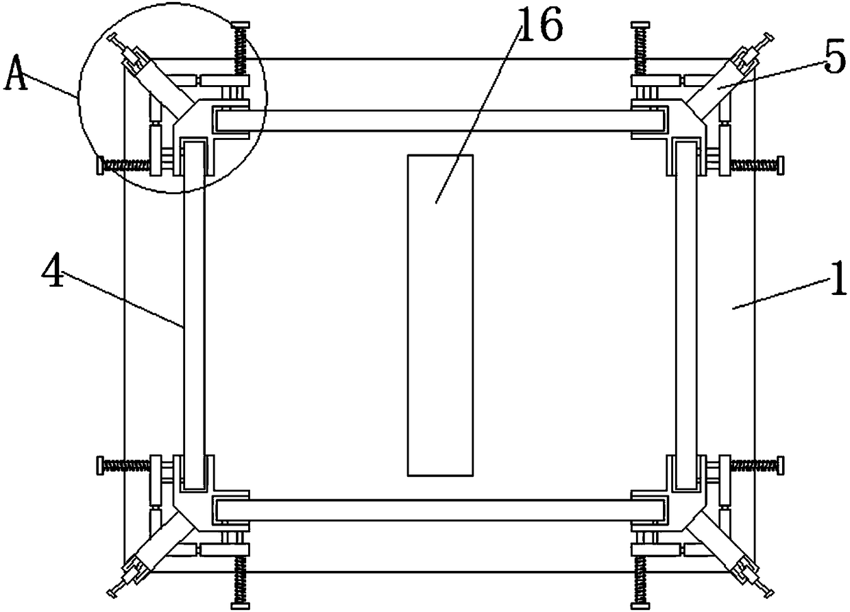
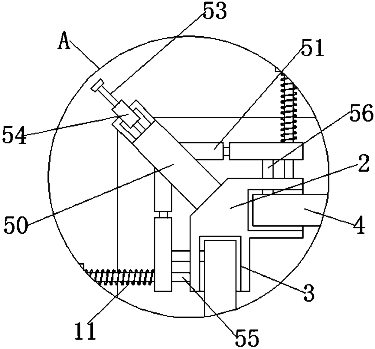
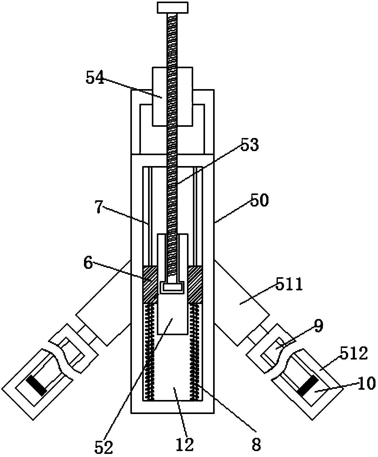
[0024] see Figure 1-8 , the present invention provides a technical solution:

[0025] A combined heat-dissipating power distribution cabinet, comprising a bottom mounting plate 1, four folded mounting seats 2 are fixedly installed near the four corners of the bottom mounting plate 1, and the two protruding sections of the folded mounting base 2 are each A mounting groove 3 is provided, and a vertical mounting plate 4 is clamped in the mounting groove 3. A pl...


PUM


Abstract

The invention relates to the technical field of power distribution cabinets, particularly to a combined heat dissipation type power distribution cabinet which comprises a bottom mounting plate, wherein four folded mounting seats are arranged on the bottom mounting plate of the combined heat dissipation type power distribution cabinet; vertical mounting plates are mounted between the folded mounting seats; top covers are mounted at top ends of the vertical mounting plates, so as to realize the combined mounting of the power distribution cabinet. The vertical mounting plates are fixed by mounting plate fixing devices on the folded mounting seats; a division plate is arranged in the middle of the bottom mounting plate; a rotating shaft connected with a motor is arranged in the division plate. The combined heat dissipation type power distribution cabinet realizes circulation of air inside a cabinet body by rotating fan blades on the rotating shaft so as to achieve an effect of dissipating heat, cools the cabinet body by blown-out cold airflow through a condensing tube penetrating the fan blades, and realizes that the airflow permeates every corner of the cabinet body by wind folding plates on both sides of the rotating shaft, so that the area covered by cold airflow is wider, and a better heat dissipating effect is achieved.

Description

technical field [0001] The invention relates to the technical field of power distribution cabinets, in particular to a combined heat dissipation type power distribution cabinet. Background technique [0002] The power distribution cabinet is a relatively common type of electrical equipment. The power distribution cabinet is used in many occasions. Some power distribution cabinets are installed outdoors. Outdoor power distribution cabinets are often exposed to sunlight, and the temperature inside the cabinet is often relatively high. There are many kinds of electrical components installed inside the upper power distribution cabinet. These electrical components emit a lot of heat when they work, which further increases the temperature inside the cabinet. If the heat is not dissipated in time, it will affect the internal temperature of the cabinet. The normal operation of electrical components, and the existing power distribution cabinets are generally integrated factory design...

Claims


Application Information

Patent Timeline
Patent Type & Authority Patents(China)
IPC IPC(8): H02B1/56H02B1/30
CPCH02B1/301H02B1/565
Inventor 孙玉平
Owner HENAN HONGDA TELECOM EQUIP
Why Eureka
Try Eureka